Expert area Part 2: Overview of display values and settings
38
Installation
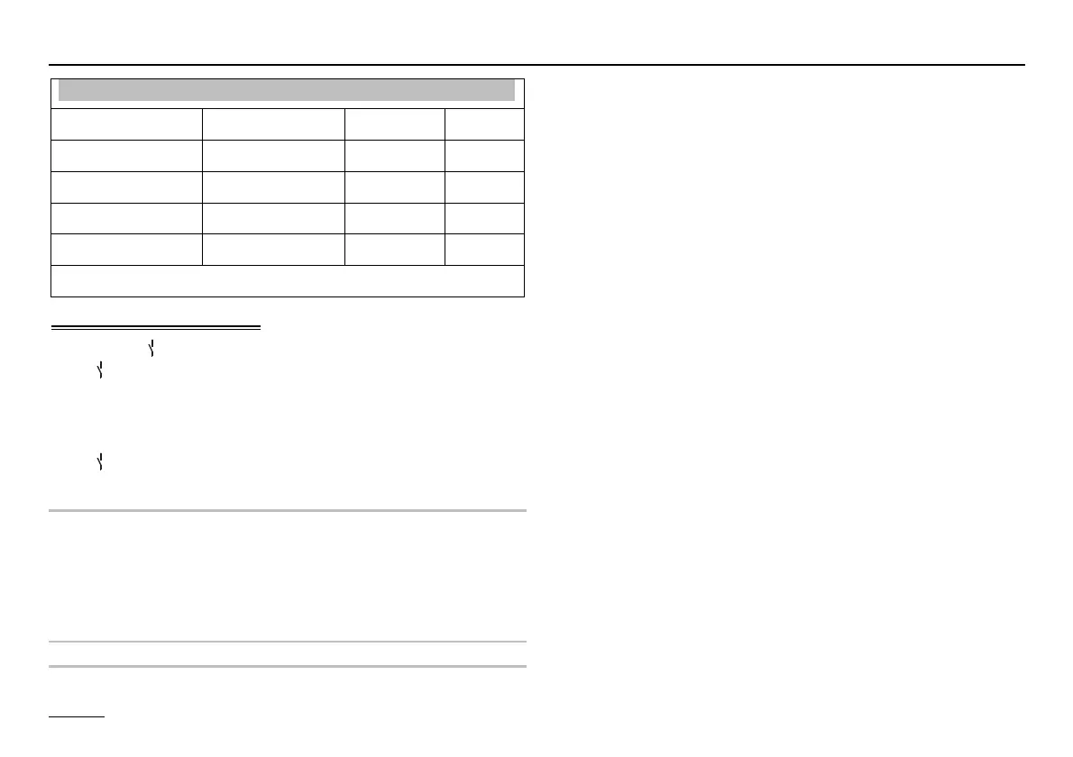
Designation Value range Default IV
FUNC RELAY 1 00 – 32 01
T-MF1 30 °C – 90 °C 30 °C
HYST MF 1 2 K – 10 K 5 K
FUNC RELAY 2 00 – 06 02
See following pages for continuation
Auxiliary relay functions
The sensor 1 (connector VIII, pin 1 + 2) is assigned to the
relay
1 (temperature-controlled) (also see page 17). If a
further sensor is required for a function, this sensor must
be connected to connector III, pin 2 + 3.
Functions which do not require a sensor are assigned to
relay
2 (timer-controlled).
FUNC RELAY 1 (function selection relay 1)
! If the parameter "LOAD THROUGH" is activated at
the level EXPERT=>HOT WATER, the additional
functions with sensor integration are not possible
(function 20 – 32)
T-MF1 (Switching temperature relay 1)
HYST MF 1 (Hysteresis relay 1)
00 = no function
01 = Header pump
ON: When heat is requested by a consumer
OFF: Without consumer heat request
If at least one consumer in the system requests heat the
pump is switched on. The after-run function is effective af-
ter the heat generator is switched on.
02 = Circulation (time)
The circulation pump is switched on according to the circu-
lation or hot water program (parameter "CIRCL-P-DHW“ at
the level USER=>HOT WATER).
03 = Booster pump
ON: In the event of a heating request from an internal con-
sumer OFF: Without internal consumer heating request A
pump after-run occurs.
05 = Pump heat generator 1
When using the controller to control two heat generators
the relay may be used to control the heat generator pump
for heat generator 1.
(Relay switches with burner relay 1; run-down = 5 min)
06 = HS pump heat generator 2
When using the controller to control two heat generators
the relay may be used to control the heat generator pump
for heat generator 2.
(Relay switches with burner relay 2; run-down =5 min)