Part 4: Installation and Start-up Installation
61
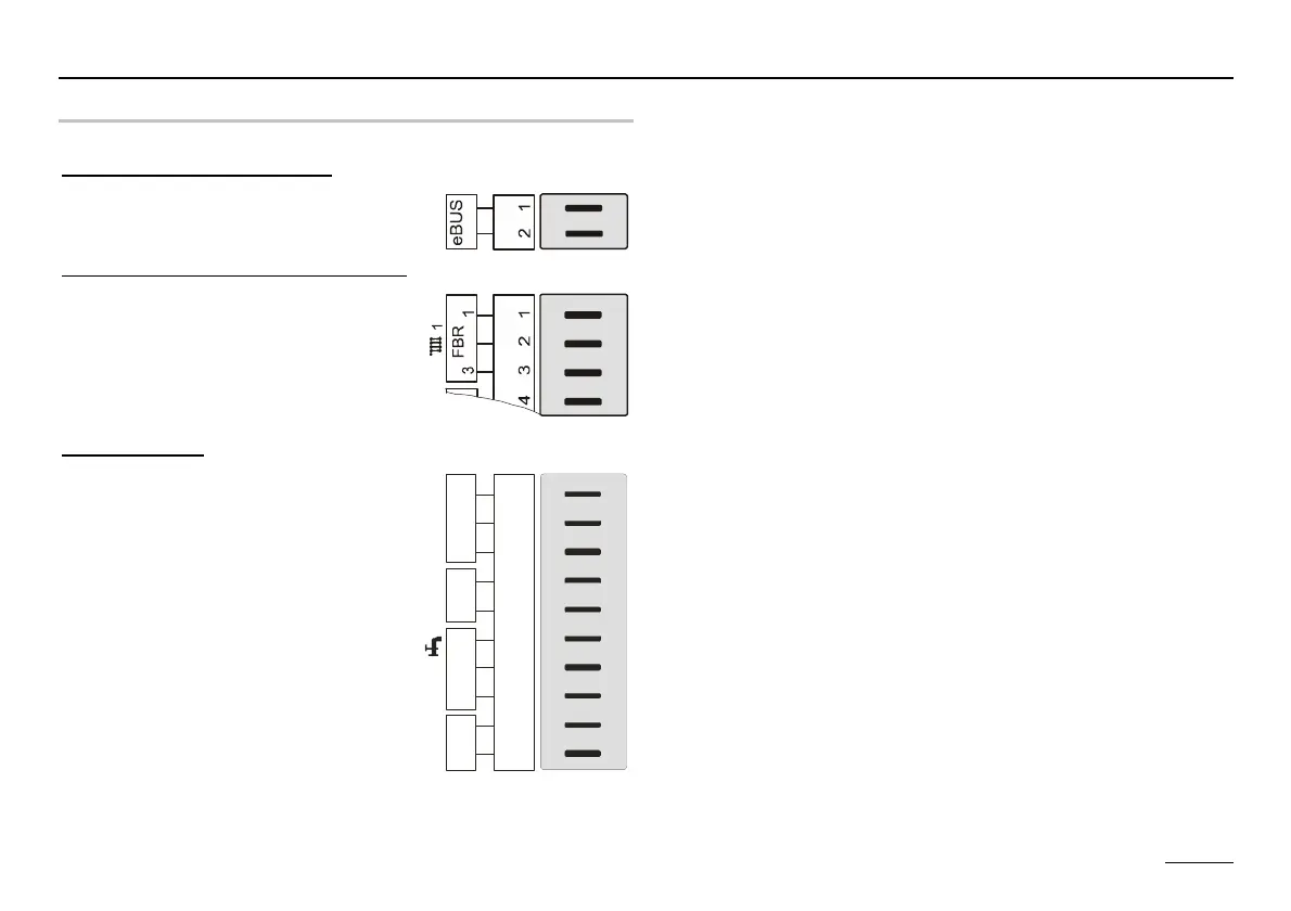
Sensor terminal assignments
Connector 7 [VII] with eBUS
VII
+
_
FA
Connector 1 [I] for HC as HW circuit
I
-
Connector 1 [I]
1
2
3
4
5
6
7
8
9
1
0
VF
AF
H
D
D
2
1
1
I
3
FB R
-
KF /SP F
Pin 1: eBUS (HS) or eBUS - DCF
Pin 2: eBUS (ground)
Pin 1: Storage tank sensor flow
Pin 2: (ground)
Pin 3: Storage tank sensor lower
Pin 1: FBR heating circuit 1 (room sensor)
Pin 2: FBR heating circuit 1 (ground)
Pin 3: FBR heating circuit 1 (set value/operating mode)
Pin 4: Flow sensor, heating circuit 2 (ground)
Pin 5: Flow sensor, heating circuit 2
Pin 6: Waste water sensor
Pin 7: Waste water and boiler sensor (ground)
Pin 8: Boiler sensor
Pin 9: Outdoor sensor (ground)
Pin 10: Outdoor sensor