Installation Part 4: Installation and Start-up
58
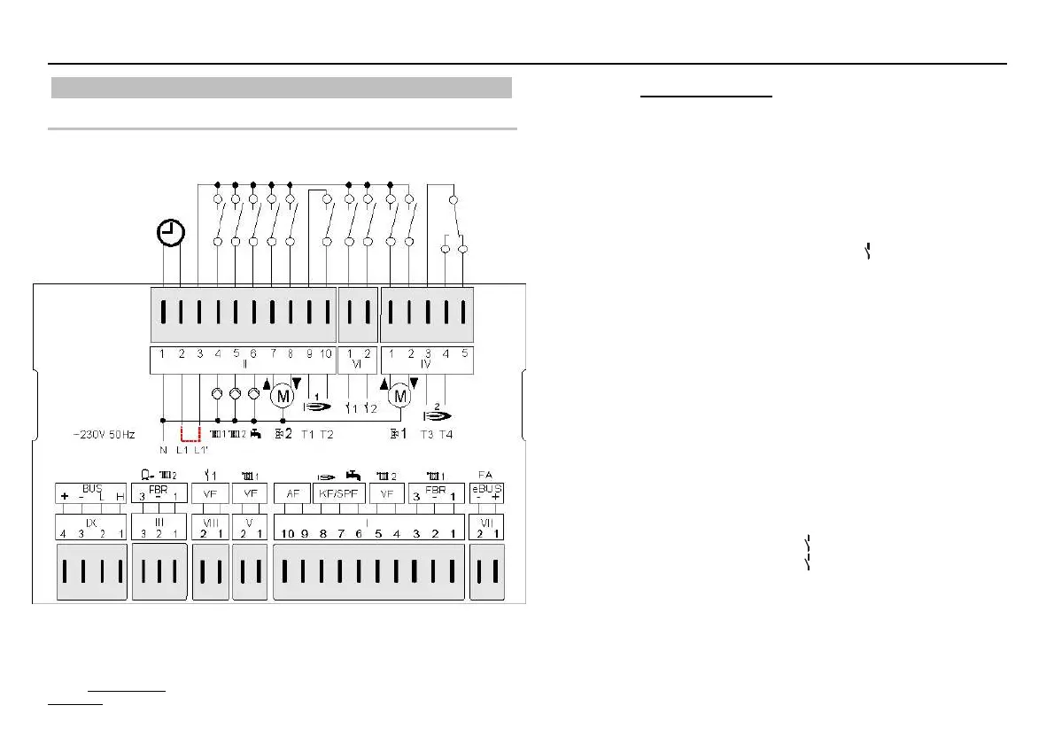
Electrical connection
Version 1
~230 V; Relay switching capacity 2(2) A, ~250 V
Terminal wiring
VII (1 + 2): eBUS (HS) or eBUS - DCF
I (1 - 3): FBR2 (FBR1) for heating circuit 1
I (4 + 5): Flow sensor, heating circuit 2
I (6 + 7): Storage tank sensor
I (7 + 8): Boiler sensor
I (9 + 10): Outdoor sensor
V (1 + 2): Flow sensor, heating circuit 1
VIII (1 + 2): Sensor multifunction relay
1
III (1 - 3): FBR2 (FBR1) for heating circuit 2
III (2 + 3): Lower buffer sensor
IX (1 + 2): Data line CAN bus
IX (3 + 4): Power supply CAN bus
II (1): Neutral conductor, mains
II (2): Power supply, unit
II (3): Power supply, relay
II (4): Pump, heating circuit 1
II (5): Pump, heating circuit 2
II (6): Storage tank pump
II (7): Mixer open, heating circuit 2
II (8): Mixer closed, heating circuit 2
II (9 + 10): Burner stage 1 / heat generator 1
VI (1): Multifunction relay
1
VI (2): Multifunction relay
2
IV (1): Mixer open, heating circuit 1
IV (2): Mixer closed, heating circuit 1
IV (3 + 4): Burner stage 2 / heat generator 2
Displayed connection is the maximum version .0634
E Attention: Bus lines and sensor lines are to be installed se
aratel
from su
l
lines!