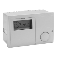
Remote controls Part 4: Installation and Start-up
64
Installation location:
In reference / main living room of the heating circuit
(on an inside wall of the room).
Not in the vicinity of radiators or other heat dissipating
units.
Any, if the room sensor influence is switched off.
Installation:
Remove cap from underside of pedestal.
Secure the base at the installation location.
Connect the electrical connection cables.
Press the cap back on.
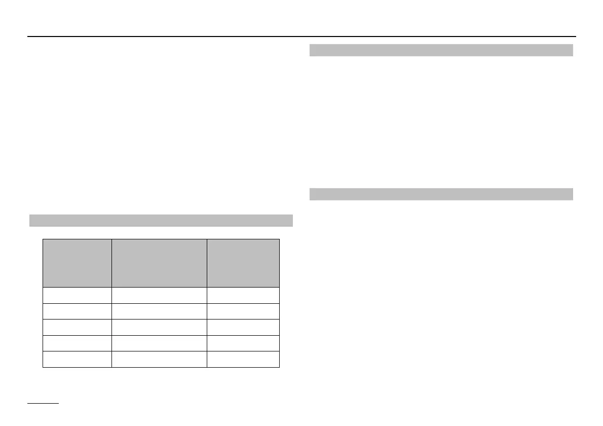
Sensor resistances FBR
DCF receiver
Electrical connection: Connector VII; 1, 2
The controller can evaluate a eBUS DCF receiver on the
eBUS FA-Terminals.
If the DCF receiver is connected, the controller time is
brought up to date daily at 03.02 and additionally 5 minutes
after switching on the voltage.
If the time does not correct itself after the specified period,
select a different location for the DCF (e.g. a different wall)
and restart the controller (switch voltage-free once).
PC
All system-specific parameters can be set and interrogated
using the
ComfortSoft parameterisation software. The pa-
rameters can be saved, displayed graphically and evaluat-
ed on the PC at predefined intervals. T connect to a PC
you need the optical adapter or CoCo PC active, which al-
so supports the sending of error messages by SMS and
the remote interrogation of controller data.
Temperature FBR1
terminals 1 - 2
switch in position q
FBR2
terminals 1 - 2
Room sensor
+10 °C 680 Ω 9.950 Ω
+15 °C 700 Ω 7.855 Ω
+20 °C 720 Ω 6.245 Ω
+25 °C 740 Ω 5.000 Ω
+30 °C 760 Ω 4.028 Ω