Part 4: Installation and Start-up Sensors
67
Sensors
Outside sensor AF (AFS) S
Order no. AF, 5 kΩ: 99 679 030
Order no. AFS, 1 kΩ: 99 679 001
Scope of supply
Outside sensor, screw and dowel
Installation location:
Wherever possible, on a northerly or north-easterly
wall behind a heated room
Approx. 2.5 m above ground
Not above windows or ventilation shafts
Installation:
Pull cover off sensor.
Fasten sensor with enclosed screw
Connect electrically
Immersion sensor KF (KFS) H/ SPF (SPFS) F
Order no. KF/SPF, 5 kΩ, 3 m, ø 6.0x50: 99 676 769
Order no. KFS/SPFS, 1 kΩ, 3 m, ø 6.0x50: 99 676 682
Installation location:
In the immersed pipe of the hot-water cylinder tank
(generally on the front face of the tank)
Installation:
Slide the sensor as far as possible into
the immersed pipe.
! The immersed sleeve must be dry.
Connect electrically
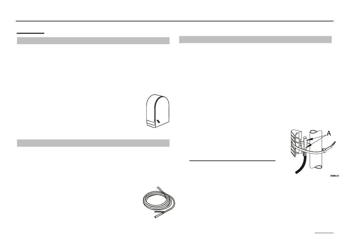
Strap-on sensor VF (VFAS) v
Order no. VF, 5 kΩ, 3 m, ø 6.0x50: 99 679 073
Order no. VFAS, 1 kΩ, 3 m, ø 6.0x50: 99 679 051
Scope of supply
Flow sensor, thermal compound, retaining strap, pressure
cap
Installation location:
In the case of boiler control instead of the boiler sensor
KF as close as possible behind the boiler on the heat-
ing flow pipe
In the case of mixer operation v approx. 0.5 m behind
the circulation pump
Installation:
Thoroughly clean the flow pipe.
Apply heat conductive paste (A)!!
Secure sensor with stretch band.
Connect electrically
! Only sensor of one type may be used