LOADING AND SECURING
144
Operating instructions • Semitrailer • 505369471-04 • 02/2019
frame", pg.138). The footing beams either
have a lock lever or a screw for securing
the system to the vehicle floor.
kg
< 10000 / 2x
> 10000 / 3x
> 14000 / 4x
> 19000 / 5x
> 24000 / 6x
2400 daN/e
e
15000 daN
max
25000 kg
15000 daN
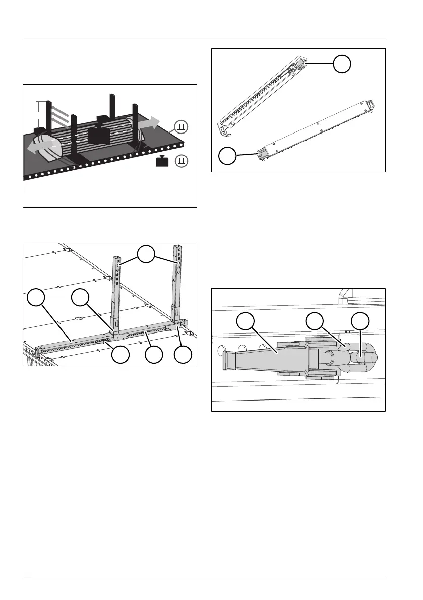
Fig.8-20: Multi Fix system
Installing the Multi Fix system
Fig.8-21: Installing the Multi Fix system
1 Footing beam with lock lever
2 Sliding shoe
3 Support beam
4 Sliding shoe
5 Footing beam without lock lever
6 Lock lever on footing beam
► Hook the footing beam without lock
lever onto the lashing holes on the
Multi Lock external frame (see "8.9.1
Using the Multi-Lock external frame",
pg.138).
Fig.8-22: Multi Fix footing beam
1 Connection profile on footing beam
with lock lever
2 Connection profile on footing beam
► Attach the footing beam with the lock
lever to the lashing holes on the op-
posite side on the Multi Lock external
frame (see "8.9.1 Using the Multi-Lock ex-
ternal frame", pg.138).
Fig.8-23: Lock lever secured on the footing
beam
1 Lock lever
2 Eyelet on lock lever
3 Hook on footing beam without lock
lever
► Open the lock lever.
► Assemble the connection profiles.
► Attach the hook on the lock lever to the
hook on the footing beam without lock
lever.
► Close the lock lever.