RUNNING GEAR OPERATION
36
Operating instructions • Semitrailer • 505369471-04 • 02/2019
Coupling
Depending on the design, the following
couplings may be installed:
○ Standard coupling heads (standard),
○ Duo-Matic coupling and
○ C-coupling heads.
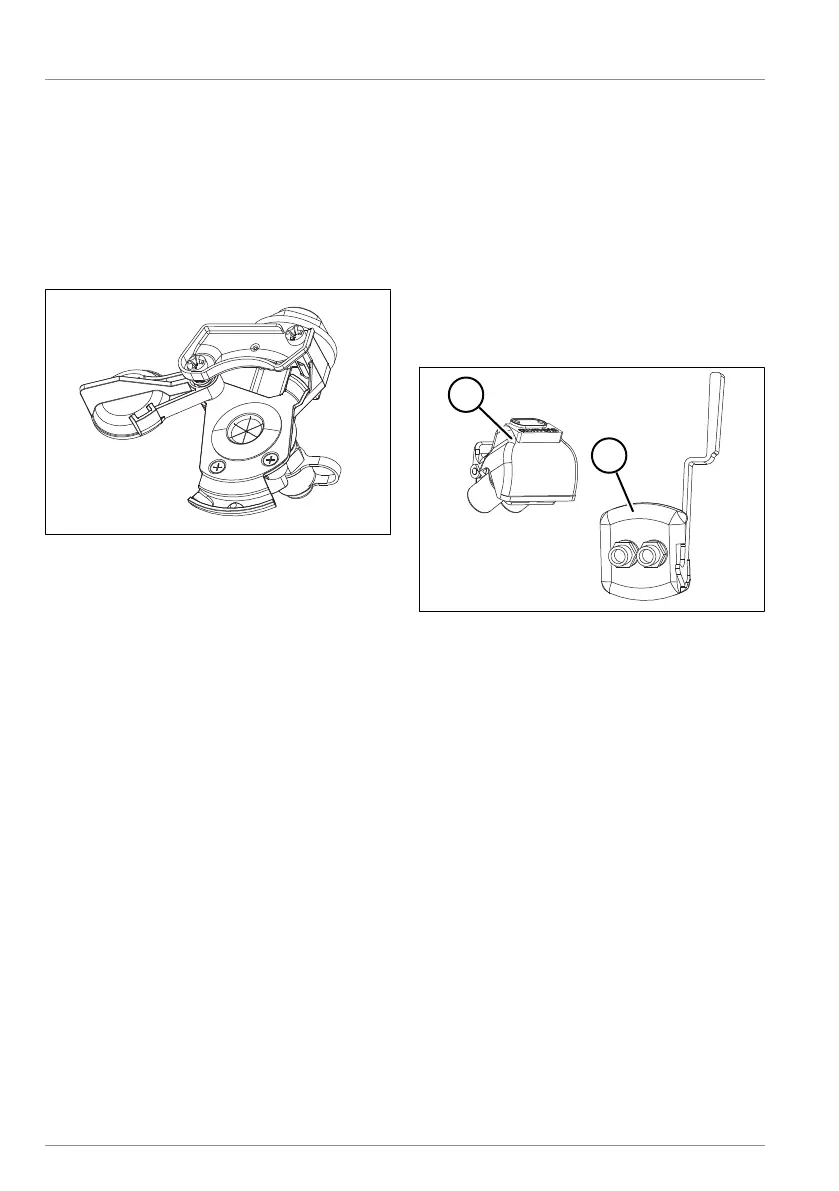
Connecting the standard coupling
Fig.5-14: Example of standard coupling
head
þ The parking brake on the tractor unit is
applied.
þ The parking brake on the trailer is ap-
plied (see "5.8.2 Parking brake", pg.40).
► Check the cleanliness and integrity of
the sealing surfaces on the coupling
heads. Clean if necessary.
► Always connect the brake compressed
air coupling (yellow) first.
► Connect the supply compressed air
coupling (red).
► Connect the power supply (vehicle
lighting) and the brake power supply
(EBS).
ü The supply and control connections
are now connected.
Disconnecting the standard coupling
þ The parking brake on the tractor unit is
applied.
þ The parking brake on the trailer is ap-
plied (see "5.8.2 Parking brake", pg.40).
► Always disconnect the supply com-
pressed air coupling (red) first.
► Disconnect the brake compressed air
coupling (yellow).
► Disconnect the power supply (vehicle
lighting) and the brake power supply
(EBS).
► Close the disconnected coupling
heads and plugs with the protective
caps.
ü The supply and control connections
are disconnected.
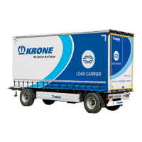
Connecting the Duo-Matic coupling
Fig.5-15: Duo-Matic coupling
1 Compressed air coupling (tractor unit
part)
2 Compressed air coupling (trailer part)
þ The parking brake on the tractor unit is
applied.
þ The parking brake on the trailer is ap-
plied (see "5.8.2 Parking brake", pg.40).
► Check the cleanliness and integrity of
the sealing surfaces on the coupling
heads. Clean if necessary.
► Pull down the compressed air coupling
(trailer part) lever and insert the coup-
ling head (tractor unit part).
► Connect the power supply (vehicle
lighting) and the brake power supply
(EBS).
ü The supply and control connections
are now connected.