Control and Display Elements
47
Pos: 26.6.1 /Überschr iften/Zwischenüb erschriften/A- E/Bei Variante Plus @ 360\mod_ 1439368214395_78. docx @ 2666056 @ @ 1
For Plus version
Pos: 26.6.2 /BA/Masc hinenbeschreibung/S chwader/elektri sch-hydraulisc he Einkreiselaushebung Mittelschwader_Bi ld @ 376\mod_14429154845 88_78.docx @ 2730705 @ @ 1
3
4
5
1
2
I
II
III
SW700087_2
6
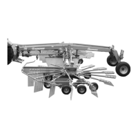
Fig. 16
Pos: 26.6.3 /Layout Modu le /--------- -------Leerzeile 5 Pt.-------------------- @ 120\mod_1342592918145 _0.docx @ 1092566 @ @ 1
Pos: 26.6.4 /BA/Masc hinenbeschreibung/S chwader/elektri sch-hydraulisc he Einkreiselaushebung _Tabelle @ 360\mod_1439368 263535_78.doc x @ 2666116 @ @ 1
The following table explains the function of the individual switches.
Switch Function
1) Warning light (red) Lit when operation panel is switched on.
2) Main switch Switch operation panel on (1) and off (0).
3) Toggle switch (inching) Set the working height on right rotor.
4) Toggle switch
Selects the rotor that is to be raised or lowered. The actual
movement is made via the single-action control unit.
Pos. I
Single-rotor lifting mechanism of left rotor:
The right rotor remains in its position. The left rotor
is raised or lowered.
Pos. II
Twin-rotor lifting mechanism:
Both rotors are raised or lowered.
Pos.III
Single-rotor lifting mechanism of right rotor:
The left rotor remains in its position. The right rotor
is raised or lowered.
5) Toggle switch (inching) Set the working height on left rotor.
6) Digital display
Minimum distance to the ground = 0 – 99 = maximum
distance to the ground.
Pos: 27 /Layout Module /---------------Seitenumbruch---------------- @ 0\mod_1196175311226_0.docx @ 4165 @ @ 1

 Loading...