To this Document
9
Pos: 13.16 /Übersc hriften/Zwischenüber schriften/P-T/Sy mbole in Abbildungen @ 336\ mod_1430121455379_ 78.docx @ 2557570 @ @ 1
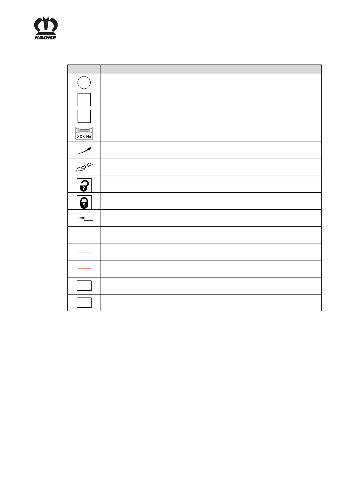
Symbols in figures
Pos: 13.17 /BA/Zu diese m Dokument/Darstell ungsmittel_Übersic ht Symbole_BA @ 329\mod_1 427193088297_78.doc x @ 2523598 @ @ 1
To visualize parts and actions steps, the following icons are used:
Icon Explanation
1
Reference sign for part
I
Position of a part (e.g. move from pos. I to pos. II)
X
Dimensions (e.g. B = width, H = height, L = length)
Action step: Tighten screws with torque key with specified tightening torque
Direction of motion
Direction of travel
opened
closed
enlargement of display detail
Framings, dimension line, dimension line limitation, reference line for visible parts
or visible mounting material
Framings, dimension line, dimension line limitation, reference line for covered
parts or covered mounting material
Laying routes
LH
Left-hand machine side
RH
Right-hand machine side
Pos: 13.18 /Layout Module /---------------Seitenumbruch---------------- @ 0\mod_1196175311226_0. docx @ 4165 @ @ 1
 Loading...