3. INSTALLATION
18
3-6. OVERHEAD SAW BLADE GUARD AND CONTROL PANEL FITTING
Overhead saw blade guard fits to saw blade with max dia. of more than 355mm.
Following is the instruction of assembly.
Note: Figure 3-6.10 shows the overall assembly points
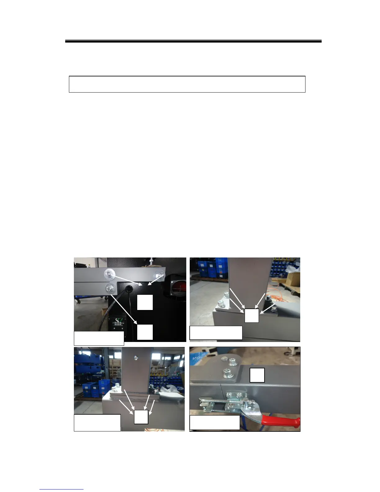
1. Screw nut in the machine frame A&B(
Fig. 3-6.1) of the support arm for overhead
guard and control panel.
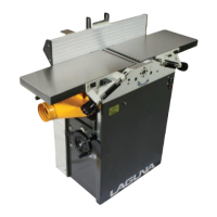
2. Screw nuts C &D (Fig. 3-6.2&3) to connect the two parts for support arm
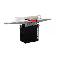
3. Lock lever E (Fig. 3-6.4) for support arm of overhead guard
4. Lock the round tube to the support arm as F ( Fig. 3-6.5)
5. Fit the hose supports on the support arm to fix the hose as G (Fig. 3-6.6)
6. Screw H(Fig. 3-6.7) for fixing saw blade guard and fix the gas spring I (Fig. 3-6.8)
7. Fix the hose on the blade guard and support arm by using hose clamp(Fig. 3-6.9)
8. Fix the cable as shown (Fig. 3-6.10) and control panel with 4 screws (K, Fig.
3-6.10).
All fitting operations in this section require approx. 3 people
Figure 3-6.1
B
A
Figure 3-6.4
E