120
9 Appendix
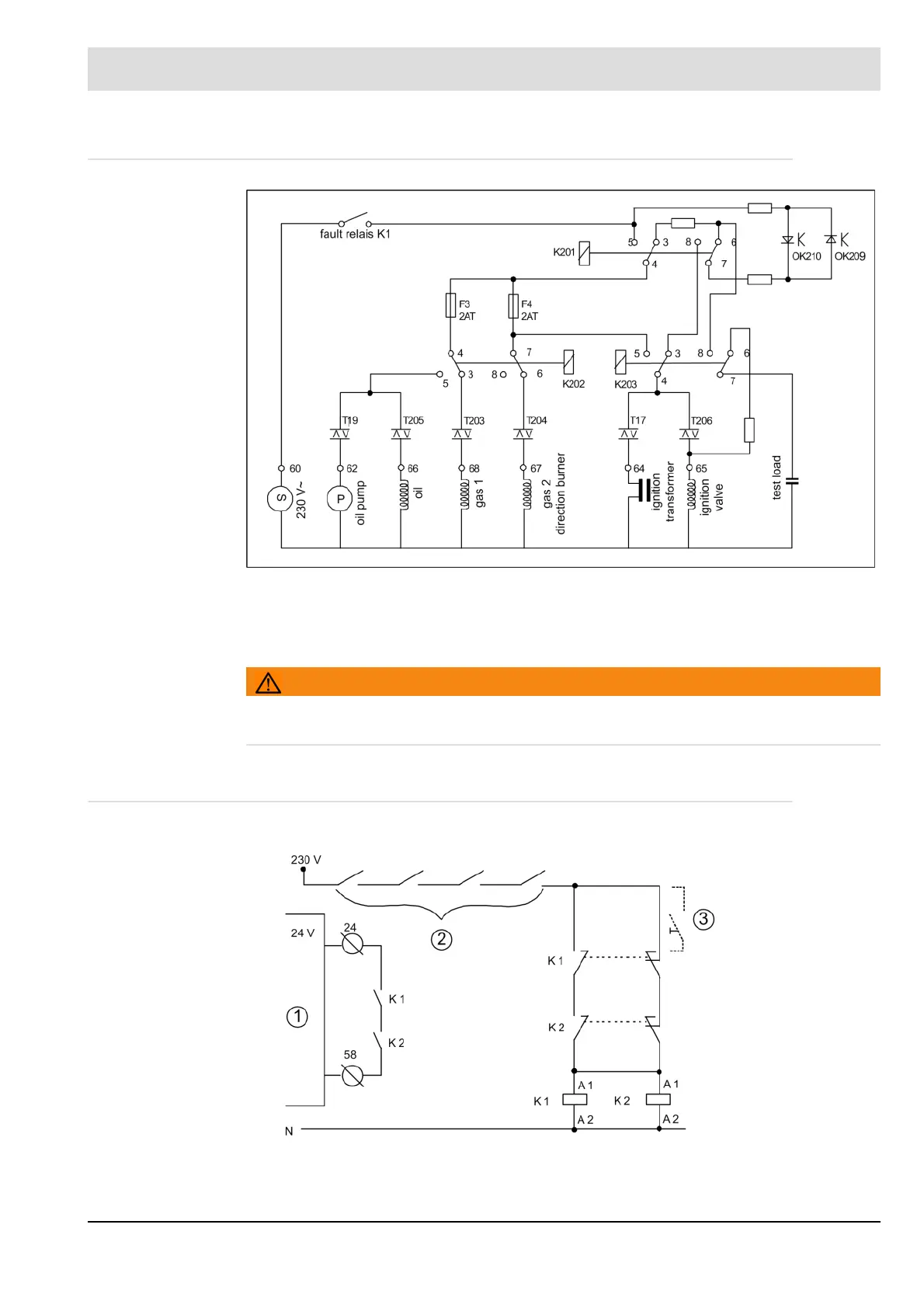
9.15 Inernal Connecting Diagram of the Control Output Device
Fig. 9-23 Internal connecting diagram of the control outputs
Always connect the attached firing rates (valves etc.) to the ETAMATIC (even when the burner
is off). If You could not ensure this, use an RC combination (ca. 0,15μF, ca. 220 ) between
the output terminal and neutral to let the testing current flow.
WARNING!
Connect the valves directly to the terminal. The activating current of the firing rate must be
much higher than 9mA
9.15.1 Interlock Chain wiring via 230 V
Fig. 9-24 Example: safety interlock chain wiring via 230 V