74
9 Appendix
9.2.2 General Information of the Optical Flame Monitoring
Notes on assembly and installation
The processes that occur during combustion give rise, inter alia, to a pulsing component of
the flame's radiation (flame flickering), whose oscillations (flame frequency) are relatively rap-
id at the flame's root (i.e. near the burner's mouth) and become slower toward is tip.
For individual monitoring, the flame sensor should be aligned in that way, that the first third of
the flame is observed.
The flame sensor's correct alignment is essential for achieving a high degree of availability
and/or selectivity.
WARNING!
We recommend to lay the supply cable, including their extension, on separate cable trays to
keep mains and control lines as well as high-energy power lines and equipment separated
from each other (e.g. ignition lines, ignition transformer, electrical motors, contactors). More-
over, avoid any parallel cable routing together with mains cables in trays
9.2.3 Optical Flame Sensors
9.2.3.1 Switching to Display the Flame Intensity
FFS07, FFS05 (is replaced by FFS07) and subtypes.
The sensor's circuit components are located on printed circuit board (PCBs) in a cylindrical
housing with a spray-proof, axial optical aperture.
The sensor meets the requirements of protection class IP 65.
Optical flame sensor FFS08, FFS06 (is replaced by FFS08) and subtypes (standard sensor
for ETAMATIC)
The sensor's circuit components are located on printed circuit boards (PCBs) in a cylindrical
housing with a spray-proof, lateral optical aperture. The sensor meets the requirements of pro-
tection class IP 65.
The computing circuit for all sensor types is located in the ETAMATIC.
Cabling from the sensor to the ETAMATIC is 5-pole, static-screened with the sensor housing's
potential (operating earth connection), a six
th
cable is for measuring the flame signal during
commissioning.
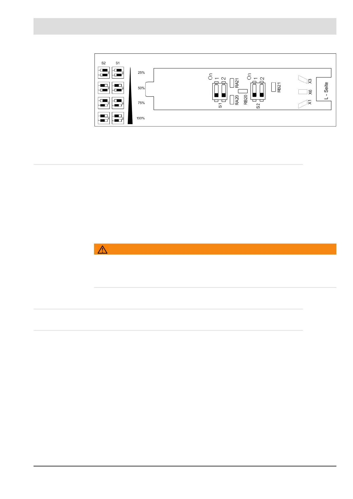
FFS06
(up to January 2014,
replaced by FFS08)
Fig. 9-3 FFS08 IR, FFS06: Adjusting the flame sensitivity - factory settings IR 50%)