16
www.lannerinc.com
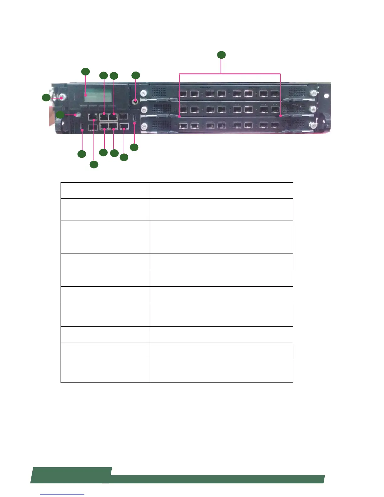
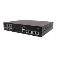
Front Components
Component Description
F1 Console
RJ-45 console port for connecting to a computer terminal
for local, out-of-band diagnostic or configuration
purpose.
F2 LCM
128 x 64 Graph LCM with 4 key pad•
Hinge LCM•
1 LED for power, 1 LED for Status and 1 LED for HDD•
F3 USB 2.0 Ports USB 2.0 type A connectors.
F4 Onboard Management Port RJ-45 onboard management port
F5 IPMI ports IPMI ports
F6 LCM Unlock Button
Push it to unlock LCM pad to access the two 2.5” drive
bays
F7 ESD Jack 1 x ESD Jack
F8 GND Ground
F9 Other RJ-45/SFP+ ports
Network ports (number and type of network ports may
vary depending on the modules installed)
F2
F1
F3
F1
F5
F4
F3
F6
F9
F7
F8
F5
F4