23
www.lannerinc.com
Jumper Settings & Connectors Pin
Definitions
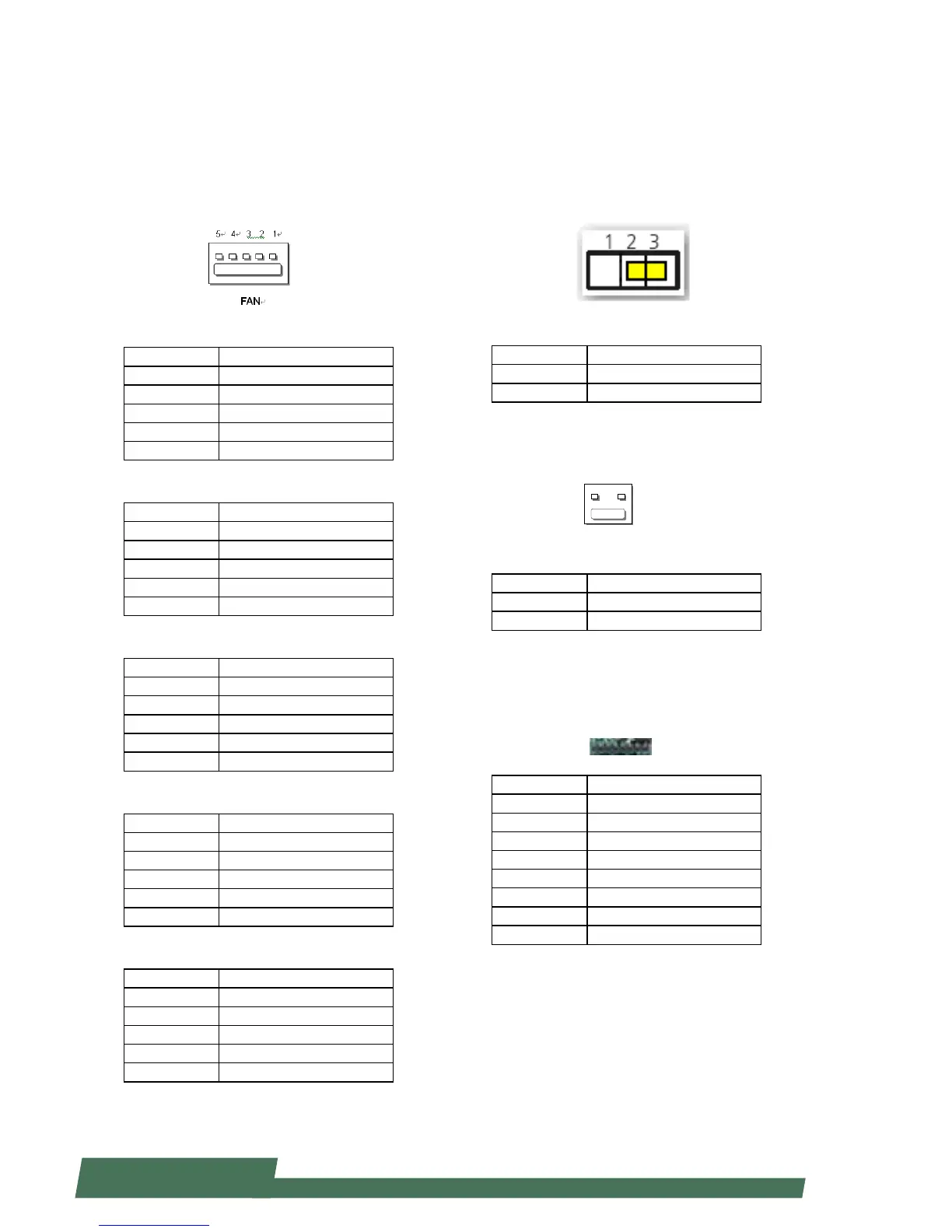
FAN connectors (FAN1~5):
Five-pin FAN connectors
FAN1
Pin Description
1 HM_PWMOUT1
2 FAN_TECH_IN_FAN1
3 FAN_TECH_IN_FAN2
4 12V
5 GND
FAN2
Pin Description
1 HM_PWMOUT2
2 FAN_TECH_IN_FAN7
3 FAN_TECH_IN_FAN8
4 12V
5 GND
FAN3
Pin Description
1 HM_PWMOUT1
2 FAN_TECH_IN_FAN3
3 FAN_TECH_IN_FAN4
4 12V
5 GND
FAN4
Pin Description
1 HM_PWMOUT2
2 FAN_TECH_IN_FAN9
3 FAN_TECH_IN_FAN10
4 12V
5 GND
FAN5
Pin Description
1 HM_PWMOUT3
2 FAN_TECH_IN_FAN5
3 FAN_TECH_IN_FAN6
4 12V
5 GND
Front Panel Reset Button Setting(J14)
The jumper setting for selecting hardware reset or
software reset. Software reset is the default option.
Pin Description
1-2 Hardware reset
2-3 Software reset (default)
Power-On Button (CONN2)
Pin Description
1 GND
2 PWR_BUTTON
CPLD Flash Pin Header (J12):
Complex Programmable Logic Device can be used to
bridge JTAG and ash memory data interface
Pin Description
1 3.3V standby
2 JIAG_PLD_TDO
3 JTAG_PLD_TDI
4 NC
5 NC
6 JTAG_PLD_TMS
7 GND
8 JTAG_PLD_TCK