4: Installation of xSenso 21A2
xSenso User Guide 30
LED Indicators
The Analog Input LEDs, the Analog Output LEDs, the Ethernet LEDs, and the Diagnostic “X” LED
are all located on the front panel of the xSenso device (Figure 4-3).
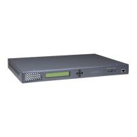
Figure 4-2 xSenso 21A2, Front View
Figure 4-3 xSenso 21A2 Top/Front View
Table 4-4 and Table 4-5 below explain the LED information displayed in Figure 4-2 and Figure 4-3
above.
Analog Analog
Output Input
LEDs LEDs
USB Ethernet Reset
Port Port
Ethernet LEDs
L R
Diagnostic
“X” LED
 Loading...