54
LAUNCH PAD V
User's Manual
PWS-3
Tap
button to perform simulation test.
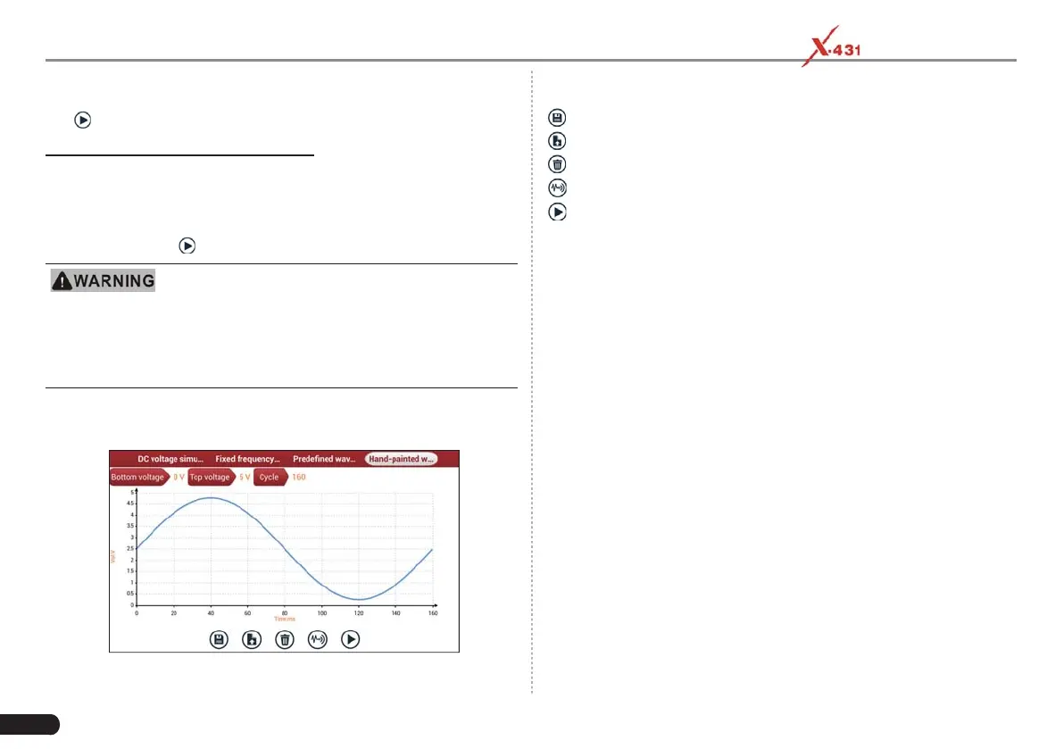
4. Hand-painted waveform simulation
This option offers great convenience for users to simulate special
waveform or fault wave. Users only draw the shape of waveform which
needs to be simulated in central drawing area, and then configure
some parameters on the top, namely high level, low level, and cycle of
waveform, then tap
, the tablet will output a waveform as desired.
Just draw a complete periodic waveform (when it is
outpuƩ ed, the system will regard the waveform in the drawing area as a
periodic one). Users should draw as large as wave in drawing zone so that
the system can sample more points to reduce tolerance. While drawing,
just pay attention to the shape of waveform, high level, low level and
period can be ignored, which can be set in the Confi gure opƟ on.
On the main menu screen, tap “Hand-painted waveform simulation”, a
screen similar to the following fi gure will appear.
Button descriptions:
[ ]: Save the current waveform.
[
]: Loads the previously saved hand-drawn waveform.
[
]: Clear all hand-drawn waveform.
[
]: Tap to call out the predefi ned waveform for reference.
[
]: Continues the following operation.
7.1.3.3 Precautions on checking vehicle sensor
• Hold the connector when plugging or unplugging it. Do not pull the
cable for unplugging.
• At fi rst check the fuse, fusible line and terminals. Then check others
after eliminating these faults.
• When measuring voltage, the ignition switch should be on and the
battery voltage should not be less than 11V.
• When measuring voltage, please shake the lead lightly in the
vertical and horizontal direction for more precision.
• When checking whether there is open in the line, disconnect the
CEU and the relevant sensor at fi rst, then measure the resistance
among the ports of sensor in order to determine whether open-
circuit / contact fault exists or not.
• When checking if there is a short in the line, please disconnect the
CEU and the relevant sensor, then measure the resistance value of
the ports between the connected port and the vehicle body. If the
resistance value is more than 1MΩ, no fault occurs.
• Before disassembling the engine electrical control system cable,
cut off the power supply, that is, turn the ignition switch OFF and
disconnect the cables on the battery poles.
• Contact the test probe and the two terminals/ the two leads to be
measured when measuring the voltage between the two terminals
or the two leads.
• Contact the red test probe to the terminal/ the cable to be