76
LAUNCH PAD V
User's Manual
Probe Compensator
Ground Connector
5. Tap the button located on the bottom of the screen, a square
wave (approximately 1kHzm 2V peak-to-peak) will be displayed
within several seconds.
*Note: The above steps also can be applied to check whether the signal
input/output of other Channels are normal or not.
Check the shape of the displayed waveform to determine whether
the probe is correctly compensated.
Correctly
Compensated
Over
Compensated
*Note: If necessary,
use a non-metallic tool
to adjust the trimmer
capacitor of the probe for
the fattest square wave
being displayed on the
Scopebox.
Under
Compensated
To avoid electric shock while using the probe, make sure
the insulated cable is perfect, and do not touch the metallic portions of the
probe head while it is connected with a high-voltage source.
7.3.3.2 Connection
For different applications, the connection methods may vary.
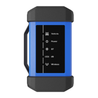
1. Power the Scopebox on: Power is provided to the Scopebox in
either of the following ways:
• Power adapter: Insert one end of the power adapter into the
Power interface of the Scopebox, and the other end to the AC
outlet.
• Battery clamps cable: Plug one end of the power adapter into
the Power interface of the Scopebox, and then clamp the other
two terminals to the vehicle's battery (Red to +, and Black to -)
respectively.
2. Connect the B-shaped terminal of the data cable to the Scopebox
Data I/O port, and the other end to the Data I/O port of the
diagnostic tool.
A. While testing sensors or actuators,
3. Connect the BNC connector of the BNC to 4mm test lead to the
CH1/CH2/CH3/CH4, and plug the black (GND) and red (SIGNAL)
4mm connectors into the Black (GND) and other color (SIGNAL)
banana sockets of the 6-way breakout leads respectively.