LAUNCH PAD V
User's Manual
77
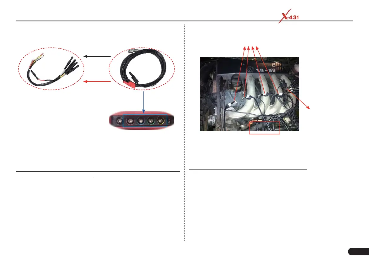
Black connector
to Black socket
Red connector
to the other color
socket
Connect to
any Channel
BNC to 4mm
test lead
Scopebox
6-way breakout lead
4. Connect the black terminal and signal wire (its other end connected
to the red 4mm connector) of the 6-way breakout lead to the GND
and signal terminal of the vehicle sensor.
B. While testing Secondary-distributor ignition analysis/Secondary-
simultaneous ignition analysis,
3. Connect the BNC connector of the secondary ignition pick-up to
any channel of the Scopebox, and clamp the crocodile clips and
high-voltage clips onto the vehicle ground and high-voltage line
respectively.
The connection is as follows:
High-voltage clips to
high-voltage line
Crocodile clips
to ground
BNC Connectors
to Channels
For detailed operations, please refer to Chapter 7.4.
C. While testing Secondary-direct ignition analysis,
3. When the high-voltage wire is exposed, plug the BNC end of
secondary ignition pickup into CH1/CH2/CH3/CH4 channel of
Scopebox, then connect the high-voltage clip to high-voltage line,
and crocodile clips to ground.
4. If no high-voltage wire is exposed, dismantle ignition coil of tested
cylinder. Connect one end of the COP extension cord to the ignition
coil which should be grounded via COP earth cord, and insert the
other end into the cylinder to joint with spark plug. Then plug the
BNC end of secondary ignition pickup into CH1/CH2/CH3/CH4
channel of Scopebox, and then connect the high-voltage clip to