28 User Manual - LCR Pro1/Pro1 Plus - ver 1.06
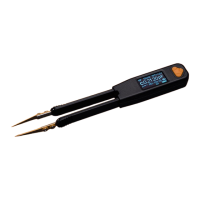
Figure 3-9: Display of C measurement
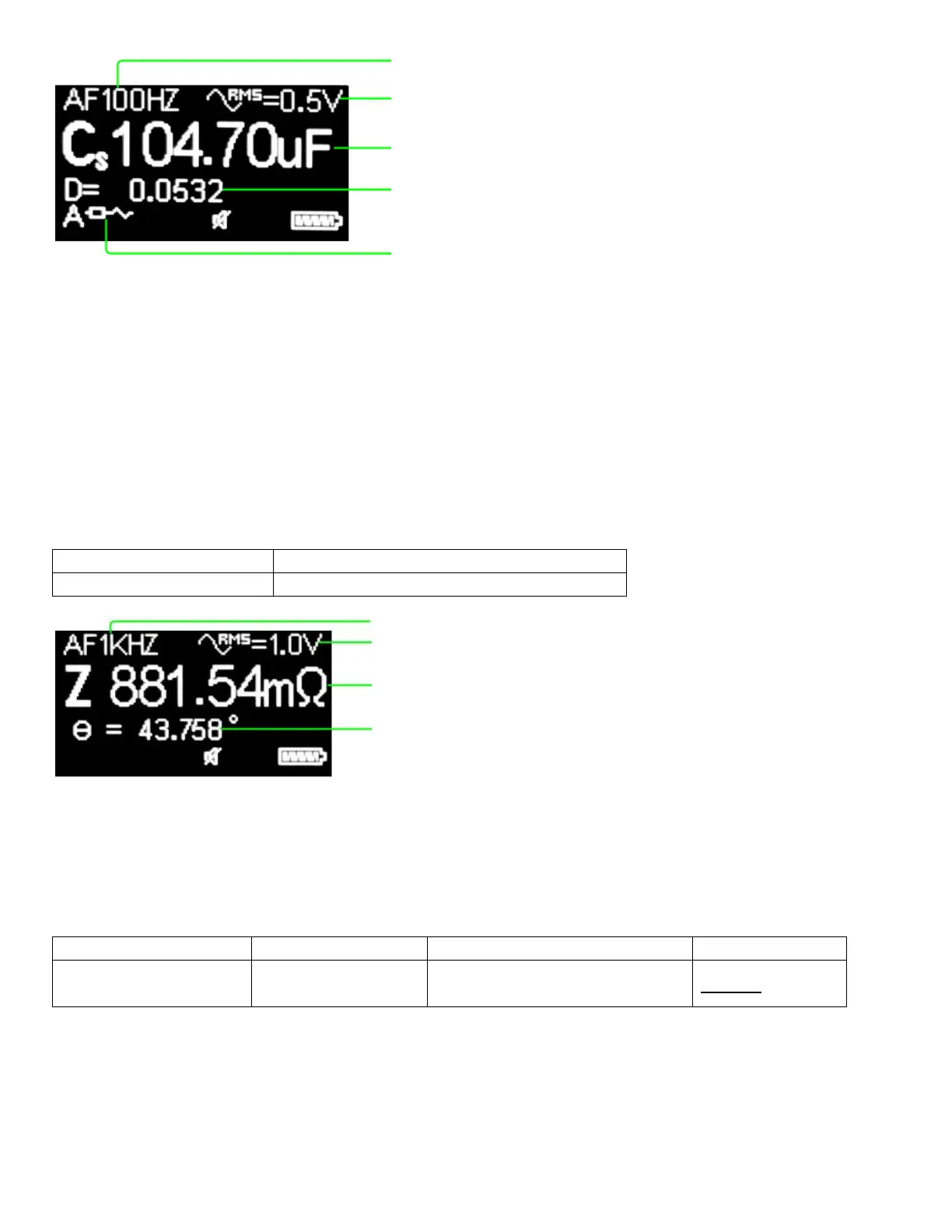
Measuring Impedance (Z)
The impedance measurement is used to measure the combination of Resistance (R) and Reactance (X) and is
measured in ohms (Ω). All circuit components, resistors, capacitors, and inductors have parasitic components,
such as unwanted inductance in resistors, unwanted resistance in capacitors, unwanted capacitance in inductors,
etc. Thus, simple components should be modeled as complex impedances. In Z mode, the meter shows phase
angle (θ) as the secondary parameter.
Table 3-6 describes how to set up the meter to measure impedance.
Table 3-6: Set Up Impedance Measurement
Main Menu -> Measurement -> LCRZ -> Z
Figure 3-10: Display of Z measurement
Selecting Secondary Parameters
Table 3-7 describes how to set up secondary parameters from the main menu.
Table 3-7: Set Up Secondary Parameter
Main Menu -> Measurement ->
SEC. PARAM.
If resistance mode (Rs-Rp) is selected, the meter shows Rs when circuit mode is selected as series and shows Rp
when circuit mode is selected as parallel. If dissipation or quality factor mode (D-Q) is selected, the meter shows
D when measuring capacitance and shows Q when measuring inductance.
Component type and measurement result
(double click the "Select" button to switch)
Secondary parameter
(single click the "Down" button to switch)
Circuit mode (double click the "Down" button to
switch)
Test voltage (double click the "Up" button to
switch)
Test frequency (single click the "Up" button to
switch)
Component type and measurement result
(double click the "Select" button to switch)
Test voltage (double click the "Up" button to
switch)
Test frequency (single click the "Up" button to
switch)