27 User Manual - LCR Pro1/Pro1 Plus - ver 1.06
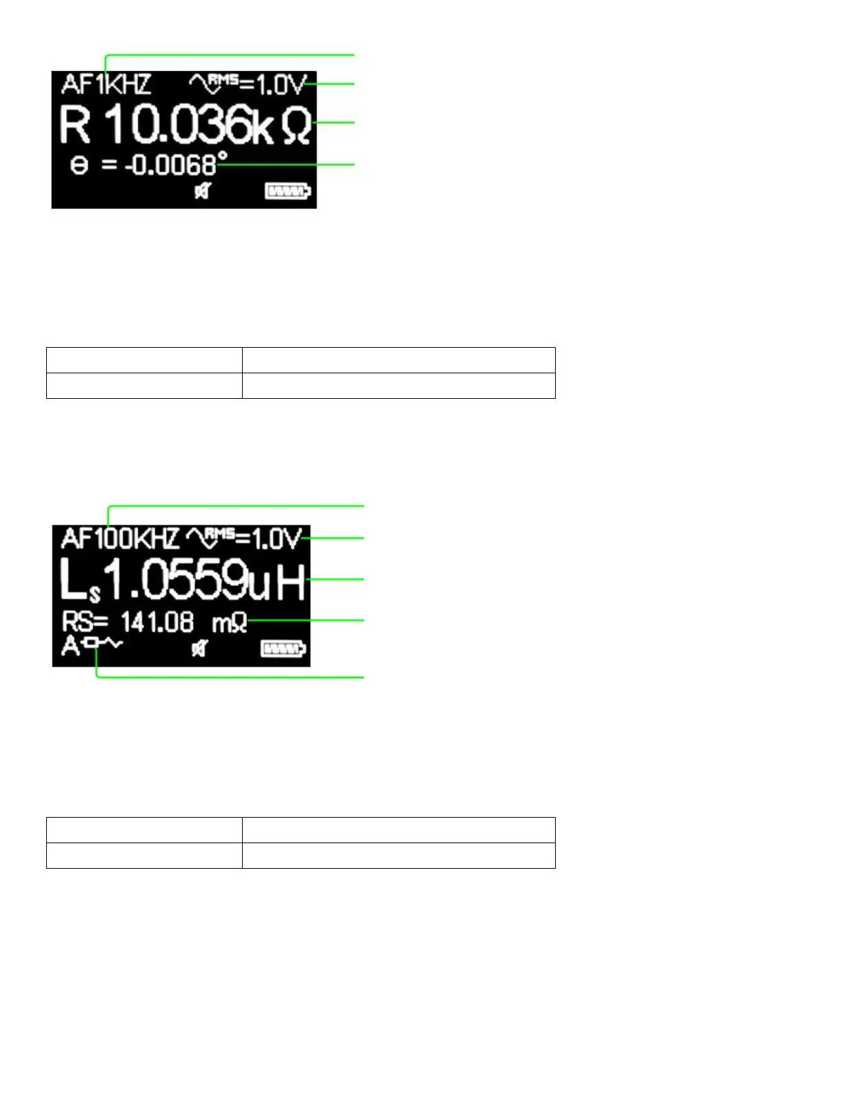
Figure 3-7: Display of R measurement
Measuring Inductance (L)
Table 3-4 describes how to set up the meter to inductance measurement.
Table 3-4: Set Up Inductance Measurement
Main Menu -> Measurement -> LCRZ -> L
In L mode, the component type shows Ls when circuit mode is selected as series and shows Lp when circuit
mode is selected as parallel. If auto circuit mode is selected, series circuit mode will always be used for
inductance measurement.
Figure 3-8: Display of L measurement
Measuring Capacitance (C)
Table 3-5 describes how to set up the meter to capacitance measurement.
Table 3-5: Set Up Capacitance Measurement
Main Menu -> Measurement -> LCRZ -> C
In C mode, the component type shows Cs when circuit mode is selected as series and shows Cp when circuit
mode is selected as parallel. If auto circuit mode is selected, series circuit mode or parallel circuit mode will be
automatically identified. See Table 3-9 for the series/parallel rules used.
Component type and measurement result
(double click the "Select" button to switch)
Test voltage (double click the "Up" button to
switch)
Test frequency (single click the "Up" button to
switch)
Component type and measurement result
(double click the "Select" button to switch)
Secondary parameter
(single click the "Down" button to switch)
Circuit mode (double click the "Down" button to
switch)
Test voltage (double click the "Up" button to
switch)
Test frequency (single click the "Up" button to
switch)