31 User Manual - LCR Pro1/Pro1 Plus - ver 1.06
menu screen.
Diode Measurement
The diode measurement is used to test a diode. Connect the meter tips across the component under test. If the
meter detects it is a good diode, it shows diode polarity and its forward voltage vs the current flowing through
the diode. If a faulty condition is detected, the meter shows one of the following messages:
• Open: High impedance is detected, i.e. an open circuit failure diode.
• Short: Short circuit is detected, i.e. a short circuit failure diode.
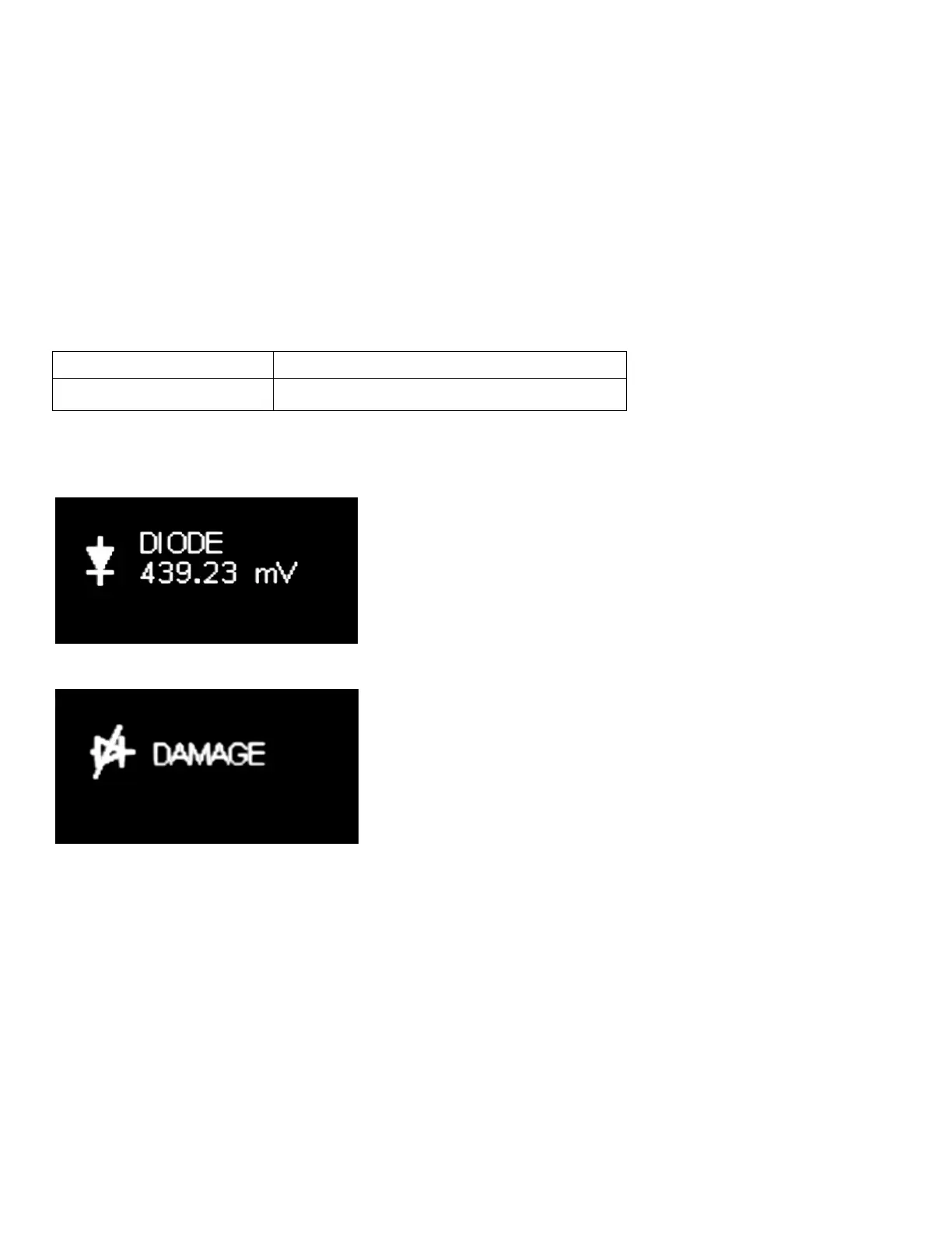
• Damage: Neither high impedance nor short circuit is detected, but the component under test doesn’t
show proper diode functions. It could be a partially damaged diode.
Table 3-14 describes how to select diode settings from main menu.
Table 3-14: Parameter Settings in Diode Measurement
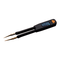
Figures 3-13 shows a typical display when a good diode is detected. Figures 3-14 shows a typical display when a
damaged diode is detected.
Figure 3-13: Display of Diode Measurement (Good Diode)
Figure 3-14: Display of Diode Measurement (Damaged Diode)
During diode measurement, user can press down the "Select" button for half second or so to go to the main
menu screen.
The LCR Pro1 Plus device is able to test LEDs. It lights up the LED and displays its electrical parameters, such as
polarity, forward voltage and forward current. When testing bi-directional LEDs, the electrical parameters will be
displayed in each direction. Figures 3-15 shows a typical display during LED testing.