14
UserManualforELD2Servo
12 DI9 Input
Digital input signal 9, default value is Path1 select
signal in position mode , low level available in
default , max voltage is 24V input 20KHz
13 DO1+ Output
Positive differential output1,24V,
100mA
Default
Alarm
output
14 DO1- Output
Negative differential output1,24V
15 DO2+ Output
Positive differential output1,24V,
100mA
Default
brake
output
16 DO2- Output
Negative differential output1,24V
17 DO3 Output
Digital output signal 3 , default value is servo-on
output (S-on) in position mode, ,24V, 8mA
18 DO4 Output
Digital output signal 4 , default value is positioning
complete (INP) in position mode,24V, 8mA
19 DO5 Output
Digital output signal 5 , default value is at torque
signal,24V, 8mA
20 COMO Output Digital output signal commonality ground, 24V
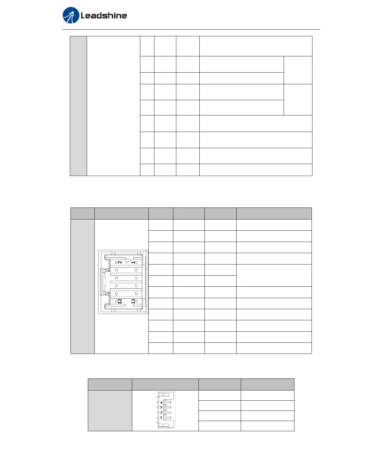
3.2.2 Encoder Input Port-CN2 Terminal
Table3.2EncoderInputPort‐CN2TerminalSignalforELD2‐400
CN2
Pin Signal IO Detail
CN2
1 SHIELD
Input
Ground terminal for shielded
2 HU
Input
Hall sensor U input
3 HW
Input
Hall sensor W input
4 HV
Input
Hall sensor V input
5 VCC
Input
+5V for encoder power supply
6 GND
Input
7 EZ+
Input
Encoder channel Z+ input
8 EZ-
Input
Encoder channel Z- input
9 EB+
Input
Encoder channel B+ input
10 EB-
Input
Encoder channel B- input
11 EA+ PE
Encoder channel A+ input
12 EA- Input
Encoder channel A- input
3.2.3 Communication Port
Table3.4SignalExplanationofconnectionanddebuggingPort
CN7
Pin
Detail
RS232
1 5V
2 TX
3 GND
4 RX