54
UserManualforELD2Servo
tech@leadshine.com for more details .
Notice:Youmustdoinspectionbeforevelocitycontroltestrun.
Table7.5ParameterSetupofVelocityControl
No Parameter Name input Setupvalue Unit
1 PA_001 Control mode setup / 21 /
2 PA_312 Acceleration time setup / User-specified millisecond
3 PA_313 Deceleration time setup / User-specified millisecond
4 PA_314
Sigmoid acceleration/deceleration time
setup
/
User-specified millisecond
5 PA_315 Zero speed clamping function select / 1 /
6
PA_300
Velocity setup internal and external
switching
/
User-specified /
7 PA_301 Speed Command direction selection / User-specified /
8 PA_302 Speed command input gain / User-specified Rpm/V
9 PA_303 Speed setting input reversal / User-specified /
10 PA_422 Analog input I(AI1) offset setup / User-specified 0.359mv
11 PA_423 Analog input I(AI1) filter / User-specified 0.01ms
12 PA_400 SI1 input selection Srv-on hex:0383 /
13 PA_401 SI2 input selection Analog hex:0001 /
14 PA_402 SI3 input selection IntSpd1 hex:0E00 /
15 PA_403 SI4 input selection IntSpd2 hex:0F00 /
16 PA_404 SI5 input selection IntSpd3 hex:1000 /
17 PA_405 SI6 input selection Vc-Sign hex:1200 /
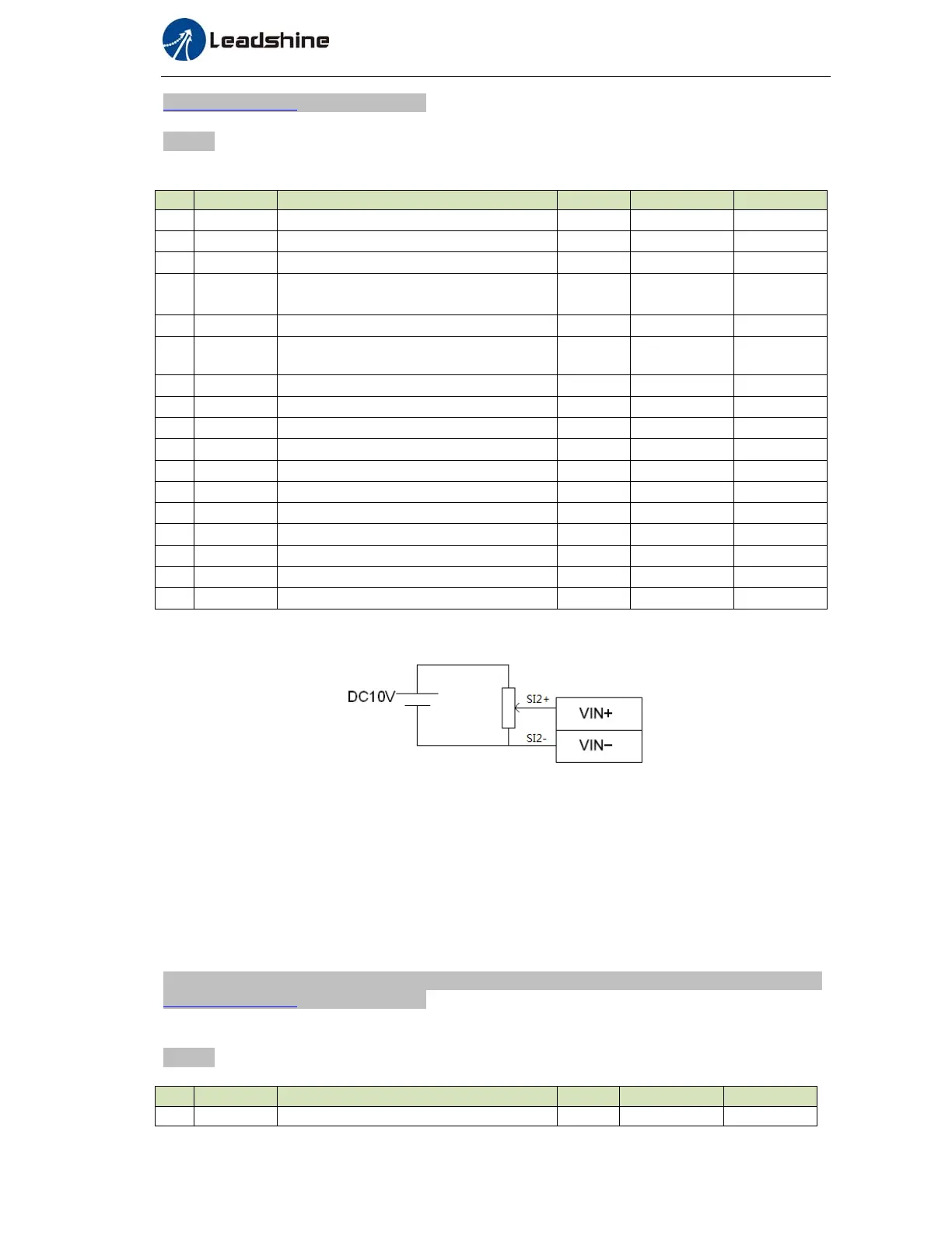
◆Wiring Diagram
◆Operation steps
1. connect terminal CN1.
2. Enter the power (DC12V to 24V) to control signal (the COM + and COM- ,while COM+ is for input
signal and COM- is for output signal).
3. Enter the power to the driver.
4. Confirm the value of the parameters, and write to the EEPROM and turn off/on the power (of the driver)
5. Apply DC voltage between velocity command input , VIN+ and VIN-, and gradually increase from 0V to
confirm the motor runs.
6.2.3 Torque Control *
The default setting of ELD2 hardware can,t support velocity mode or Torque mode , pls contact
tech@leadshine.com for more details .
Notice:Youmustdoinspectionbeforetorquecontroltestrun.
Table7.6ParameterSetupofTorqueControl
No Parameter
Name input Setupvalue Unit
1 PA_001 Control mode setup / 22 /