53
UserManualforELD2Servo
24VDC , and it is forbidden to connect these signal directly for the power of 24VDC , it will destroy the
hardware of servo driver.
6.2 Trial Run
After installation and connection is completed , check the following items before turning on the power:
Wiring?(especiallypowerinputandmotoroutput)
Shortorgrounded?
Looseconnection?
Unstablemounting?
Separationfromthemechanicalsystem?
6.2.1 Position Control
Notice:Youmustdoinspectionbeforepositioncontroltestrun.
Table7.4Par ameterSetupofPositionControl
No Parameter Name Input Value Unit
1 PA_001 control mode setup / 20 /
2 PA_312
Acceleration time setup
/
User-specified
millisecond
3 PA_313
Deceleration time setup
/
User-specified
millisecond
4 PA_314
Sigmoid acceleration/deceleration time setup
/
User-specified
millisecond
5 PA_005 Command pulse input select / 0 /
6 PA_007 Command pulse mode select / 0 /
7 PA_400 SI1 input selection Srv-on hex:0383 /
8 PA_518 Command pulse prohibit input invalidation / 1 /
SI1and SI2 function select:Pulse+Direction/Analog/GPIO
Pr4.00 Pr4.01
Direction 0 --
Pulse -- 0
Analog -- 0
GPIO1 Selectable --
GPIO2 -- Selectable
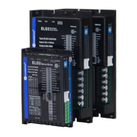
◆ Wiring Diagram
1). If the driver is enabled with internal signal, Pr403 should be set to 383, and connection of CN1 should
be set as following :
Figure7‐3ControlTerminalCN1SignalWiringinPositionControlModewithinternalservo‐onsignal
◆Operation Steps
1. Connect terminal CN1.
2. Enter the power (DC12V to 24V) to control signal (the COM + and COM-).
3. Enter the power to the driver.
4. Confirm the value of the parameters, and write to the EEPROM and turn off/on the power (of the driver)
5. Enter low-frequency pulse and direction signal to run the motor at low speed.
6.2.2 Velocity Control *
The default setting of ELD2 hardware can,t support velocity mode or Torque mode , pls contact