56
UserManualforELD2Servo
tor
ue mode
The step of changing the operation mode:
1, Switch the driver to Servo Off status.
2, Modify the corresponding parameters of control mode to EEPROM.
Turn off/on the power to make the new mode works after setup completed.
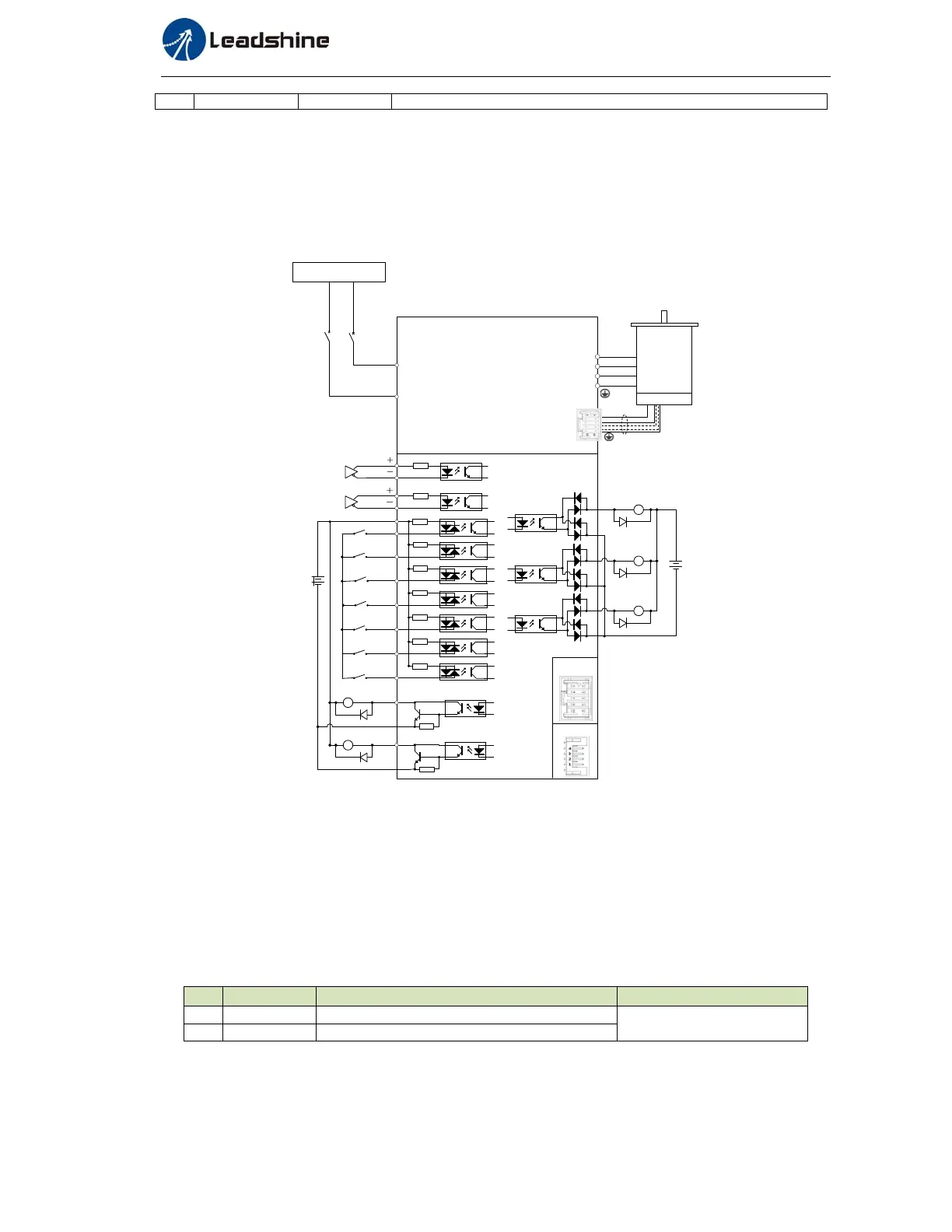
6.3.2 Position Mode
The driver is widely used for precise positioning in position control mode.
CN1
5
COM_IN
ENA
CLR
12~24Vdc
RS232
Commucation
Port
1
PUL
2
PUL
3
DIR
270Ω
4
DIR
CN2
U
PE
W
V
6
7
Vdc
GND
DC Power supply
+
-
RS485*2
270Ω
4.7K
4.7K
4.7K
4.7K
NOT
9
DOT
8
HOME
10
CTRG
11
PR1
12
4.7K
4.7K
4.7K
13
ALM+
15
BR+
ALM-
BR-
14
16
COM_OUT
24Vdc
17
18
19
20
SERVO ON
TNP
AT
Pulse
signal
Figure7‐6PositionModeTypicalWiringDiagram
Correspondingparameterssetupofpositioncontrolmode
1. Process of command pulse input
The positional commands of the following 3 types (pulse train) are available.
◆A, B phase pulse
◆Positive direction pulse/negative direction pulse
◆Pulse + Direction
Please set the pulse configuration and pulse counting method based on the specification and configuration
of installation of the host controller.
Table7.8ParameterSetupofPositionCommandSelection
No Parameter Name Setupmethod
1 PA_006 Command pulse polar setting
Please refer to chapter 4
2 PA_007 Command pulse input mode setting
2. Electronic gear function
The function multiplies the input pulse command from the host controller by the predetermined dividing or