28
UserManualforELD2Servo
4.2.3
【
Class 2
】
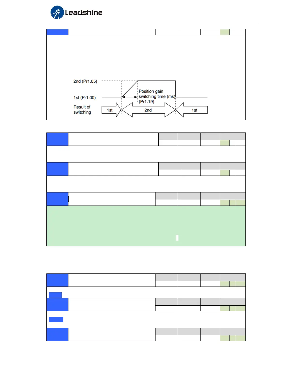
Vibration Suppression
0 -10000
0.1ms
33 P
For position controlling: if the difference between 1st gain and 2nd gain is large, the increasing rate
of position loop gain can be limited by this parameter.
<Position gain switching time>
Notice: when using position control, position loop gain rapidly changes, causing torque change and
vibration. By adjusting Pr1.19 position gain switching time, increasing rate of the position loop gain
can be decreased and variation level can be reduced.
Example: 1
st (pr1.00) <-> 2nd (Pr1.05)
Pr1.35*
Positionalcommandfiltersetup
Range unit default
Related
control mode
0 -200
0.05us
0 P
Do filtering for positional command pulse, eliminate the interference of the narrow pulse, over-large
setup will influence the input of high frequency positional command pulse, and make more
time-delayed.
Pr1.36*
pulsedigitalfilterofencoder
feedbacksetup
Range unit default
Related
control mode
0 -10000
0.1ms
33 P
Do filtering for pulse of encoder feedback, eliminate the interference of the narrow pulse, over-large
setup will influence the performance of motor in large speed, and influence the control performance
of motor causing by large time-delayed.
Pr1.37
SpecialFunctionRegister
Range unit default
Related
control mode
0 -32767
0 P S T
In binary, each bit of the register is used for some function bit operations.
Bit2:=1 Give up error of motor speed out of control 1A1
Bit4:=1 Give up error of motor over-load 100、101
Bit6:=1 Give up error of excessive vibration 190
Bit7:=1 Give up error of resistance discharge circuit over-load 120
Bit9:=1 Give up error of motor power line is out of phase 0d1( Other bit bits are disabled and
default is 0 )
Pr2.01
1stnotchfrequency
Range unit default
Related
control mode
50 -2000
HZ
2000 P S T
Set the center frequency of the 1st
notch filter
Notice: the notch filter function will be invalidated by setting up this parameter to “2000”.
Pr2.02
1stnotchwidthselection
Range unit default
Related
control mode
0 -20
-
2 P S T
Set the width of notch at the center frequency of the 1st notch filter.
Notice: Higher the setup, larger the notch width you can obtain. Use with default setup in normal
operation.
Pr2.03
1stnotchdepthselection
Range unit default
Related
control mode
0 -99
-
0 P S T