5
UserManualforELD2Servo
Table of Contents
Introduction ..................................................................................................................................................... 2
Chapter 1 Introduction .................................................................................................................................... 7
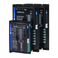
1.1 Product Introduction .......................................................................................................................... 7
1.2 Inspection of product ......................................................................................................................... 8
Chapter 2 Installation ...................................................................................................................................... 9
2.1 Storage and Installation Circumstance .............................................................................................. 9
2.2 Servo Driver Installation ................................................................................................................... 9
2.2.1 Installation Method ................................................................................................................. 9
2.2.2 Installation Space ................................................................................................................. 10
2.3 Servo Motor Installation .................................................................................................................. 10
Chapter 3 Wiring ........................................................................................................................................... 11
3.1 Wiring .............................................................................................................................................. 11
3.1.1 Wire Gauge ........................................................................................................................... 11
3.1.2 Position Control Mode ......................................................................................................... 12
3.2 Driver Terminals Function .............................................................................................................. 13
3.2.1 Control Signal Port-CN1 Terminal ....................................................................................... 13
3.2.2 Encoder Input Port-CN2 Terminal ........................................................................................ 14
3.2.3 Communication Port ............................................................................................................. 14
3.2.4 Power Port ............................................................................................................................ 15
3.2.5 Bus connector ....................................................................................................................... 15
3.2.6 Dip switch ............................................................................................................................ 15
3.3 I/O Interface Principle ..................................................................................................................... 16
3.3.1 Switch Input Interface .......................................................................................................... 16
3.3.2 Switch Output Interface ........................................................................................................ 16
3.3.3 Pulse Input Interface ............................................................................................................. 17
3.3.4 Analog Value Input Interface ................................................................................................ 18
3.3.5 Servo Motor Encoder Input Interface ................................................................................... 18
Chapter 4 Parameter ...................................................................................................................................... 19
4.1 Parameter List ................................................................................................................................. 19
4.2 Parameter Function.......................................................................................................................... 21
4.2.1【Class 0】Basic Setting ...................................................................................................... 21
4.2.2【Class 1】
Gain Adjust ........................................................................................................ 24
4.2.3【Class 2】Vibration Suppression ........................................................................................ 28
4.2.4【Class 3】Velocity/ Torque Control .................................................................................... 29
4.2.5【Class 4】I/F Monitor Setting ............................................................................................ 33
4.2.6【Class 5】Extended Setup .................................................................................................. 38
4.2.7【Class 6】Special Setup...................................................................................................... 39
Chapter 5 Alarm and Processing ................................................................................................................... 41
5.1 Alarm List ........................................................................................................................................ 41
5.2 Alarm Processing Method ............................................................................................................... 42
Chapter 6 Trial Run ....................................................................................................................................... 50
6.1 Inspection Before trial Run ............................................................................................................. 50
6.1.1 Inspection on wiring ............................................................................................................. 50
6.1.2 Timing chart on power-up .................................................................................................... 51
6.1.3 Timing chart on fault ............................................................................................................ 51
6.1.4 Holding brake ....................................................................................................................... 51
6.2 Trial Run .......................................................................................................................................... 52
6.2.1 Position Control .................................................................................................................... 52
6.2.2 Velocity Control.................................................................................................................... 52
6.2.3 Torque Control ...................................................................................................................... 53
6.3 Automatic Control Mode Run ......................................................................................................... 54
6.3.1 Operation Mode Selection .................................................................................................... 54
6.3.2 Position Mode ....................................................................................................................... 55
Chapter 7 PR function ................................................................................................................................... 58
7.1 Overview ......................................................................................................................................... 58
7.1.1 Main function ....................................................................................................................... 58