73
UserManualforELD2Servo
7.4.2 485 communication Installation wiring
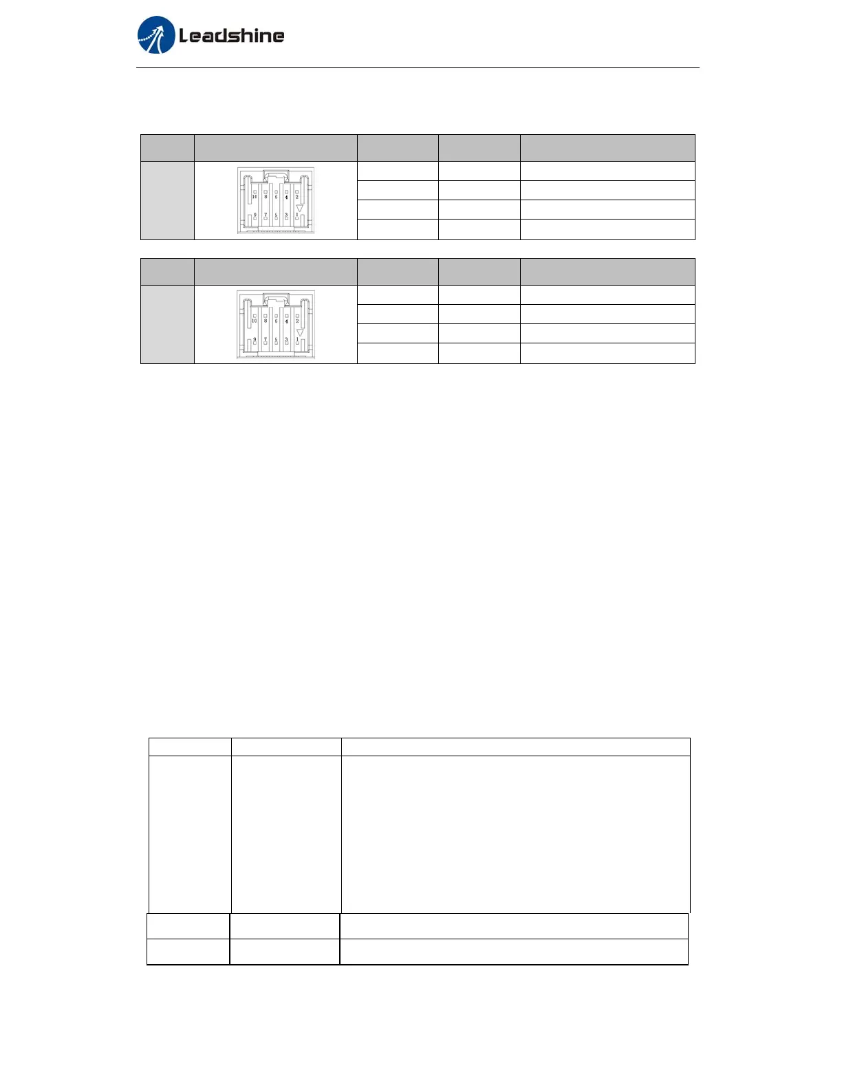
Bus connector
Cn8
Pin Signal Detail
CN8
485
IN
1 RS485+
485data+
3 RS485-
485 data-
5 485GND 485 GND
other NC
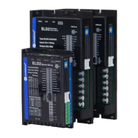
Cn9
Pin Signal Detail
CN9
485
OUT
1 RS485+
485data+
3 RS485-
485 data-
5 485GND 485 GND
other NC
Do not use CN3 communication port,that is for parameters setting only
7.4.3 Fixed trigger mode
Fixed trigger mode is to config no more than 16 segments homing and path. Then, replace
CTRG and HOME with Pr8.02(trigger register) to start the operation path. This mode apply to
fixed motion and simple operation system.
As below procedure:
1. Firstly, config homing and path 0~ path 15 which need to run, can transmit parameter
configuration temporarily after power on, also can configured to save with upper computer.
2. Enable drive.
3. Implement choice and start of actions by write corresponding instructions into 0x6002 (P8.02) .
Write 0x01P, P segment positioning (write 0x010 to run path 0, write 0x013 to run path 3)
Write 0x020,homing
Write 0x021, current position manual set to zero.
Write 0x040, E-stop.
Read 0x000p, means positioning accomplished, can receive new data
Read 0x01P, 0x020, 0x040 means still does not response to instructions.
Read 0x10P, means path is running.
Read 0x200, means instruction accomplished and wait for positioning.
Set path 0 parameters as the table showing, path 1~path15 parameters are the same as path 0
Paramete Name Specification
P900
Motion mode path 0
The model of the PR pat, to determine the action property according to
motion mode
Bit0-3: TYPE: 0 No Action /1 position addressing /2 speed running/3
homing
Bit4: INS,0 do not interrupt /1 interrupt (All interrupt now)
Bit5: OVLP,0 do not overlap /1 overlap(Null)
Bit6-7:
0 absolute position /1 relative instruction /2 Relative to the motor
Bit8-13: 0-15 Jump to the corresponding path
Bit14: JUMP: 0 do not jump /1 jump
P901-P902
Position
P901 for high 16bit,P902 for low 16bit.
P903
Speed running speed, rpm