29
UserManualforELD2Servo
Note:ForparameterswhichNo.haveasuffixof“*”,changedcontentswillbevalidatedwhenyouturn
onthecontrolpower.
4.2.4
【
Class 3
】
Velocity/ Torque Control *
Set the depth of notch at the center frequency of the 1st notch filter.
Notice: Higher the setup, shallower the notch depth and smaller the phase delay you can obtain.
Pr2.04
2ndnotchfrequency
Range unit default
Related
control mode
50 -2000
HZ
2000 P S T
Set the center frequency of the 2nd
notch filter
Notice: the notch filter function will be invalidated by setting up this parameter to “2000”.
Pr2.05
2ndnotchwidthselection
Range unit default
Related
control mode
0 -20
-
2 P S T
Set the width of notch at the center frequency of the 2nd notch filter.
Notice: Higher the setup, larger the notch width you can obtain. Use with default setup in normal
operation.
Pr2.06
2ndnotchdepthselection
Range unit default
Related
control mode
0 -99
-
0 P S T
Set the depth of notch at the center frequency of the 2nd notch filter.
Notice: Higher the setup, shallower the notch depth and smaller the phase delay you can obtain.
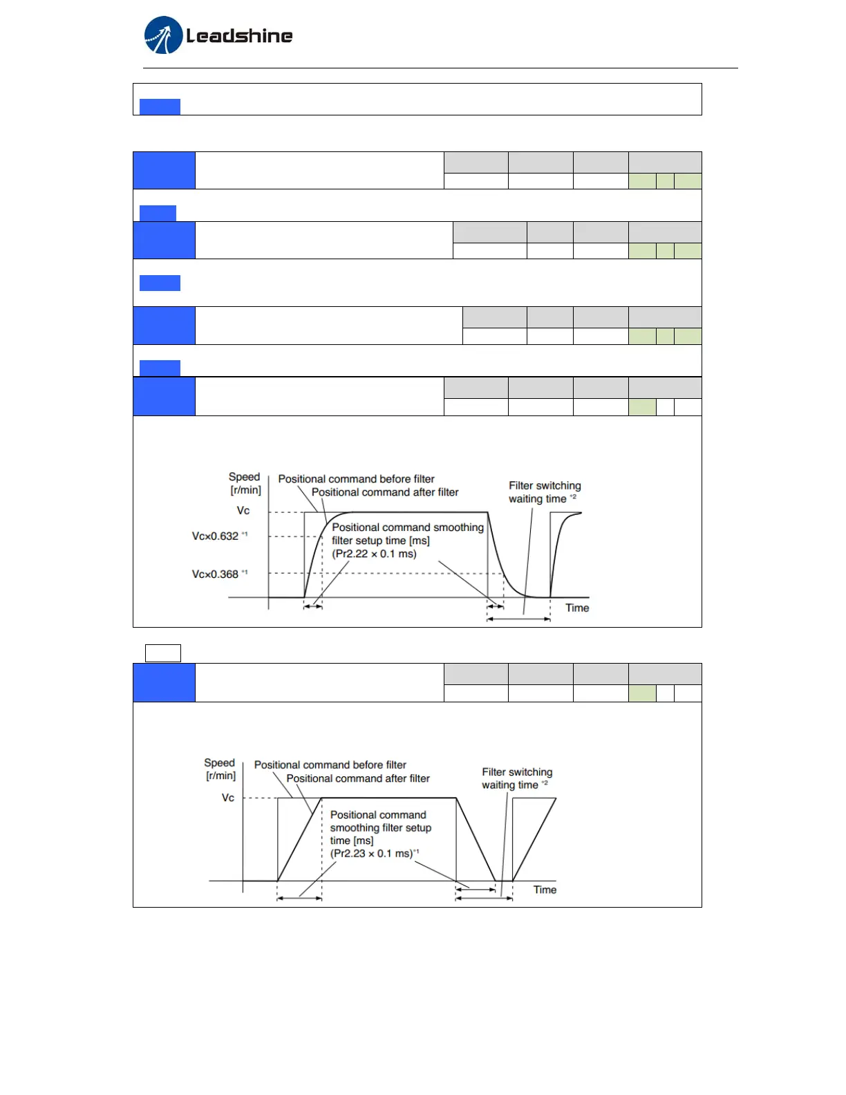
Pr2.22
positionalcommandsmoothing
filter
Range unit default
Related
control mode
0 -32767
0.1ms
0 P
Set up the time constant of the1st
delay filter in response to the positional command.
When a square wave command for the target speed Vc is applied ,set up the time constant of the
1
st
delay filter as shown in the figure below.
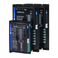
Pr2.23
positionalcommandFIRfilter
Range unit default
Related
control mode
0 -10000
0.1ms
0 P
Set up the time constant of the1st
delay filter in response to the positional command.
When a square wave command for the target speed Vc is applied , set up the Vc arrival time as
shown in the figure below.