Leidos Security Detection & Automation, Inc. – Proprietary Page 107 of 119
© 2020 Leidos. All rights reserved
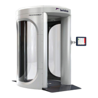
42.0 Installation of Barrier Belt Option
Figure 118: Barrier Belt
The barrier belt has two parts; belt canister and belt receiver. These are installed on either side of the
entrance.
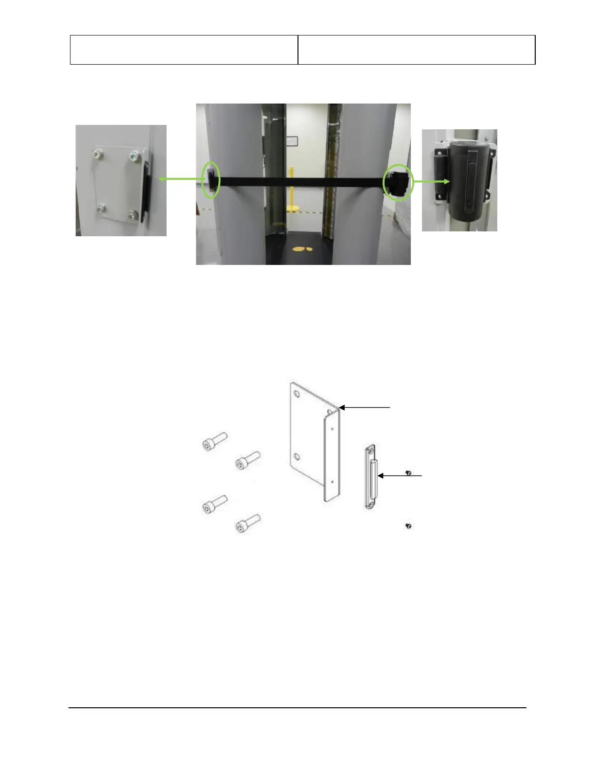
1. Attach the receiver end bracket supplied with the barrier belt (0125-20359-00) to the wall mount
angle bracket (3000-20412-00 or 3000-23604-00) using two M3-0.5x4mm PPH screws (0201-20380-
04). Refer to Figure 119.
Figure 119: Receiver End
2. Attach the wall mount-angle bracket to system entrance left side mounting holes on LCD mounting
bracket (3000-23601-00X) using four each, M8x30mm FSHC screws (0201-22862-30).
3. Loosely install four .58” spacers (3000-22751-00) to entrance right-side LCD mounting bracket using
four each, M8x30mm FSHC screws (0201-22862-30), with ¼” of threads exposed.
4. Place the barrier belt bracket 3000-20411-01 over exposed threads and slide down to lock heads into
bracket keyholes. See Figure 120. Tighten bolts. Earlier version of bracket does not have keyholes.
Assemble as required.
 Loading...