Leidos Security Detection & Automation, Inc. – Proprietary Page 28 of 119
© 2020 Leidos. All rights reserved
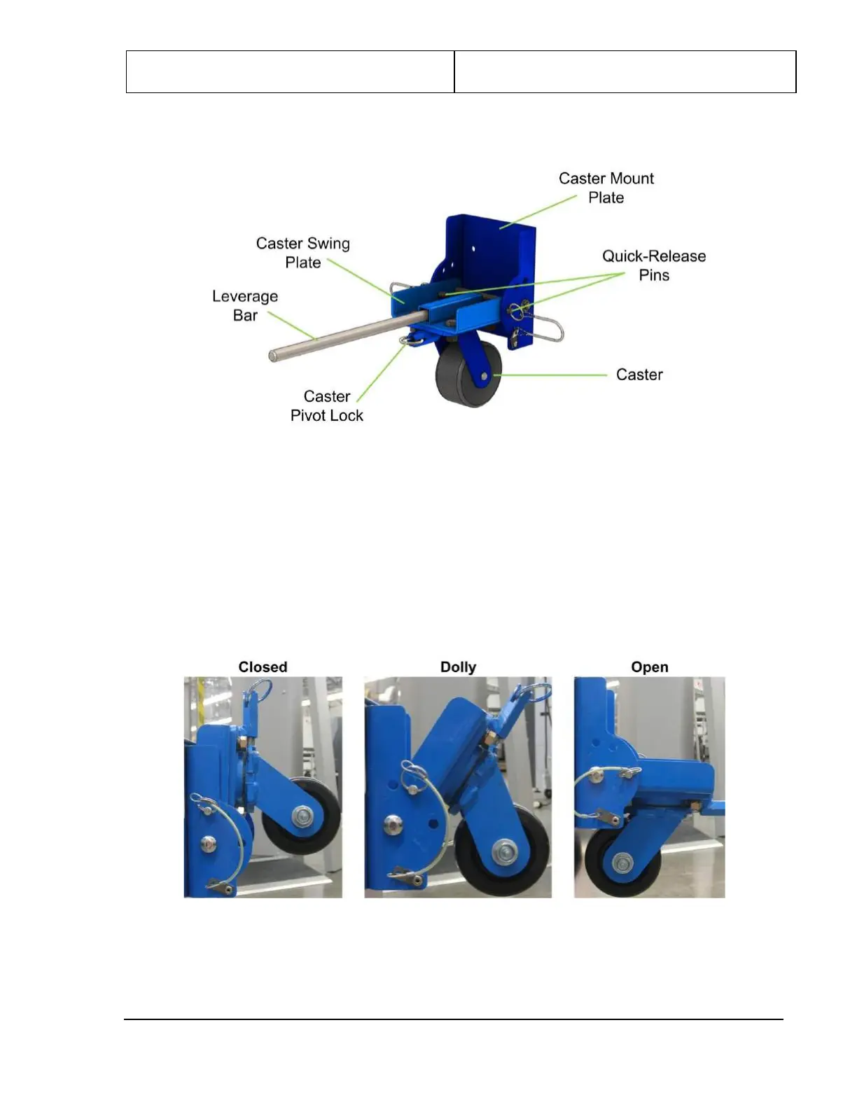
6.0 Caster Operation
Figure 15: Caster Assembly
Following are some important notes on caster operation. The step-by-step procedures are presented in the
next chapter.
1. When the caster assemblies are mounted onto the caster end plates, they must be in the “closed”
(vertical) position to access the two lower screw holes and “dolly” (intermediate) position to access
the two upper screw holes, as shown in the following figures.
When they are deployed downward to enable movement of the upper/lower frame assembly, they are
in “open” position.
Figure 16: Caster Positions