Leidos Security Detection & Automation, Inc. – Proprietary Page 39 of 119
© 2020 Leidos. All rights reserved
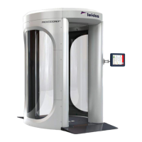
Figure 31: Columns Attached with Bolts and Column Head Clamps
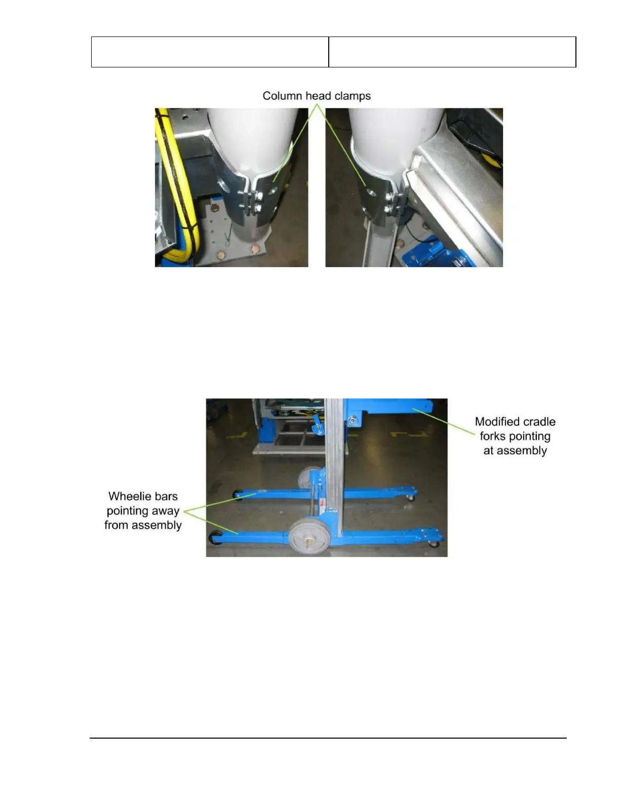
11. Position one Genie Lift (assembled in Chapter 5) at one end of the upper/lower frame assembly with
its modified cradle forks pointing at the assembly and its wheelie bars pointing away.
12. Position the other Genie Lift at the other end with its modified cradle forks pointing at the assembly
(and the other Genie Lift) and its wheelie bars pointing away.
Figure 32: Genie Lift Position
13. Lower the cradle forks on each lift until they are a few inches above the floor.
14. Move the Genie Lifts to line up the holes at the end of each modified cradle fork with the holes near
the end of each lifting bar and insert a quick-release pin to secure them, as shown in the following
figure.