Leidos Security Detection & Automation, Inc. – Proprietary Page 37 of 119
© 2020 Leidos. All rights reserved
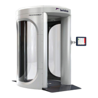
Figure 26: Lifting Bracket with Quick-Release Pin Being Inserted
3. Repeat for the second lifting bracket at the other end of the assembly.
4. Retrieve the two long rectangular lifting bars from the installation kit and insert them through the
square holes in the two lifting brackets. Lift them up and secure them in place, as shown in the
following figure, with the quick-release pins provided in the hardware kit.
Figure 27: Lifting Bar Inserted Through Lifting Bracket and Pinned in Place
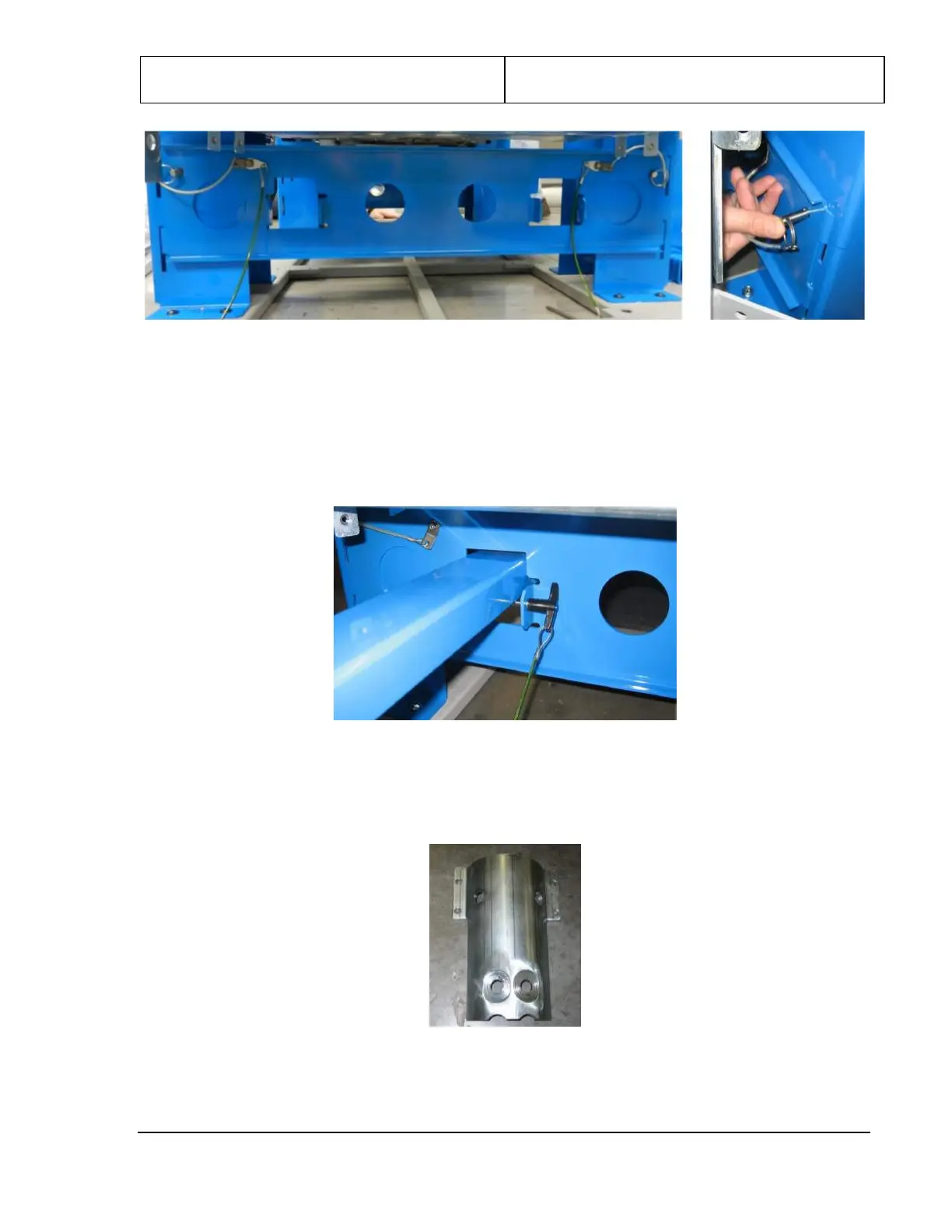
5. Remove the column head clamps (3810-10059-00), shown in the following figure, from the four
corners of the upper/lower frame assembly, set them aside along with the bolts securing them to the
upper/lower frame assembly.
Figure 28: Column Head Clamp
6. Retrieve the four columns removed from the scanner crate earlier. There are two left columns
(1000-26550-00) and two right columns (1000-26550-01). With the foot pointed toward you, the left