Leidos Security Detection & Automation, Inc. – Proprietary Page 68 of 119
© 2020 Leidos. All rights reserved
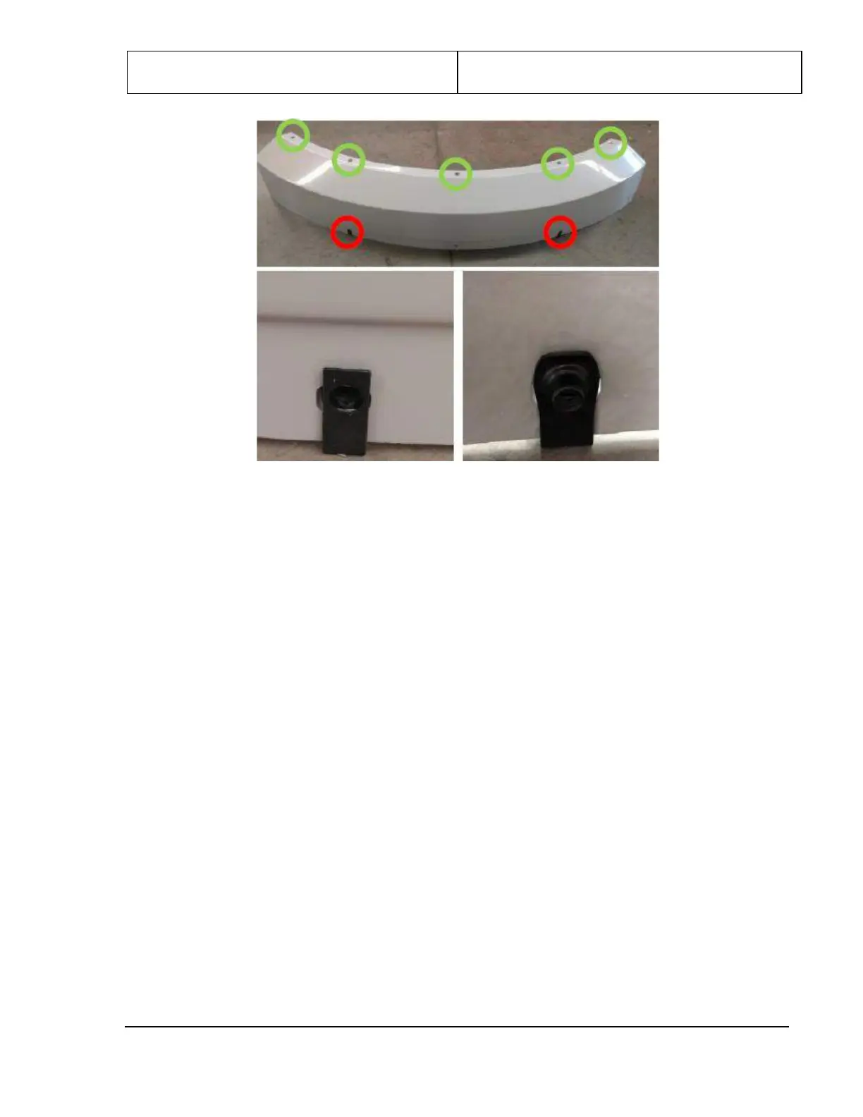
Figure 73: Top Side Cover and Clip-On Panel Nuts
3. Slide the notched end of the top side cover into the bracket at the top of the entrance/exit cover, as
shown in the following figure left.
4. Repeat steps 1 to 4 for the other top side cover.
5. Line up the holes along the top edge of the top side cover (shown circled in green in the previous
figure) with the clip-on panel nuts along either side of the roof.
Note: The hole at the bottom center and the two panel nuts circled in red is used later to fasten the
upper covers.
6. The top edge of the top side cover is fastened using five #8 x .750 PTH screws (0200-20643-12) and
five #8 flat washers (0220-20783-00). Align the top side cover as shown in the following figure right,
and then tighten the screws.