Leidos Security Detection & Automation, Inc. – Proprietary Page 36 of 119
© 2020 Leidos. All rights reserved
9.0 Upper Assembly Lift
Before beginning this procedure, ensure that the casters and caster end plates are removed.
9.1 Preparation of Assembly and Genie Lifts
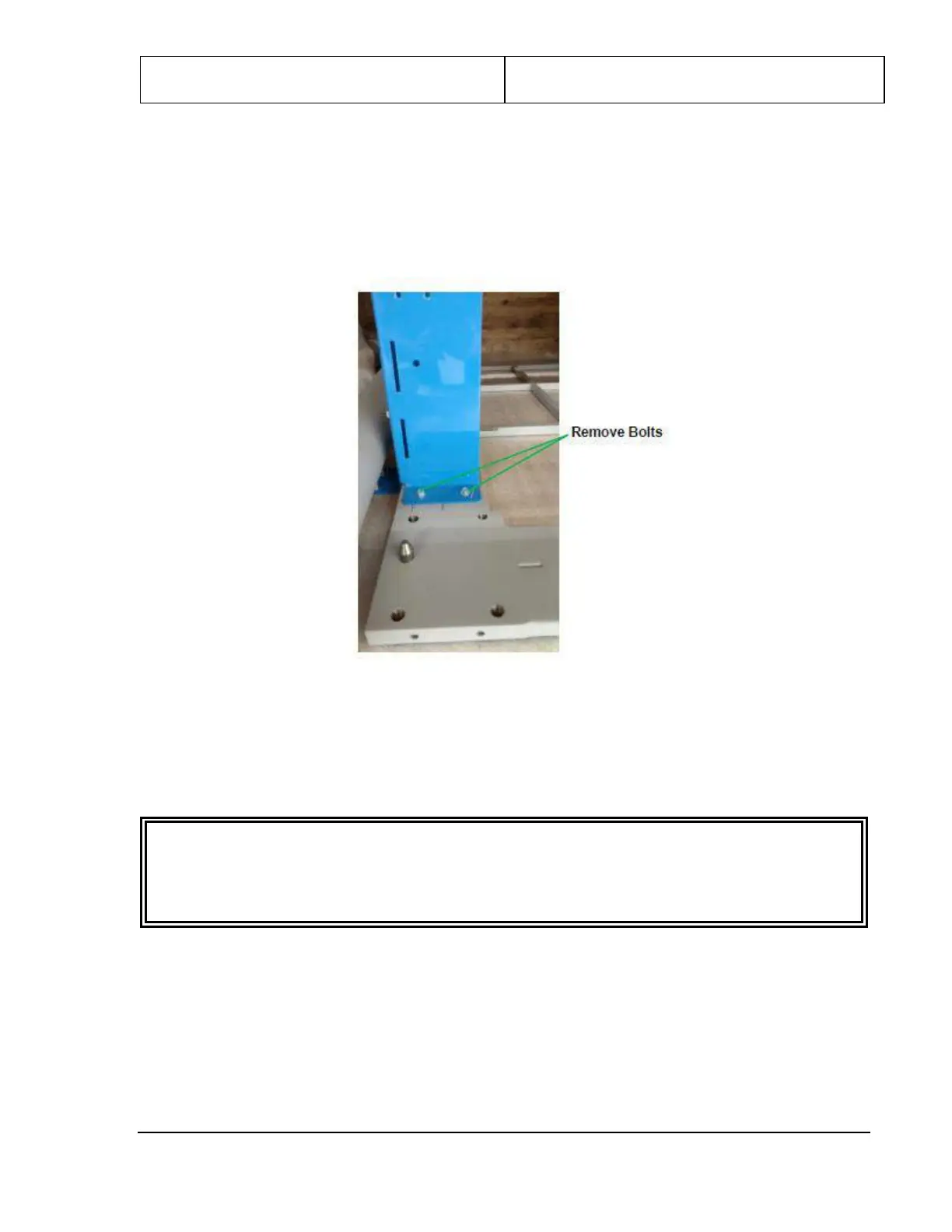
1. Remove the two “outer” bolts (nearest either end of the scanner) from each shipping leg, as shown in
the following figure.
Figure 25: Bolts to Remove from Shipping Legs
2. Retrieve the two lifting brackets [1000-11907-00] from the installation kit and attach the first between
the two shipping legs at one end of the upper/lower frame assembly. Insert the hooked tabs on the
lifting bracket into the slots on the side of the two shipping legs nearest this end and lift upward, then
insert the quick-release pin, as shown in the following figure.
CAUTION
Do not attempt to insert lifting bars or lift the upper/lower frame assembly without having quick-
release pins securing the lifting bracket in the locked position. Equipment damage and injury can
result from failing to lock the lifting bracket in the correct position.