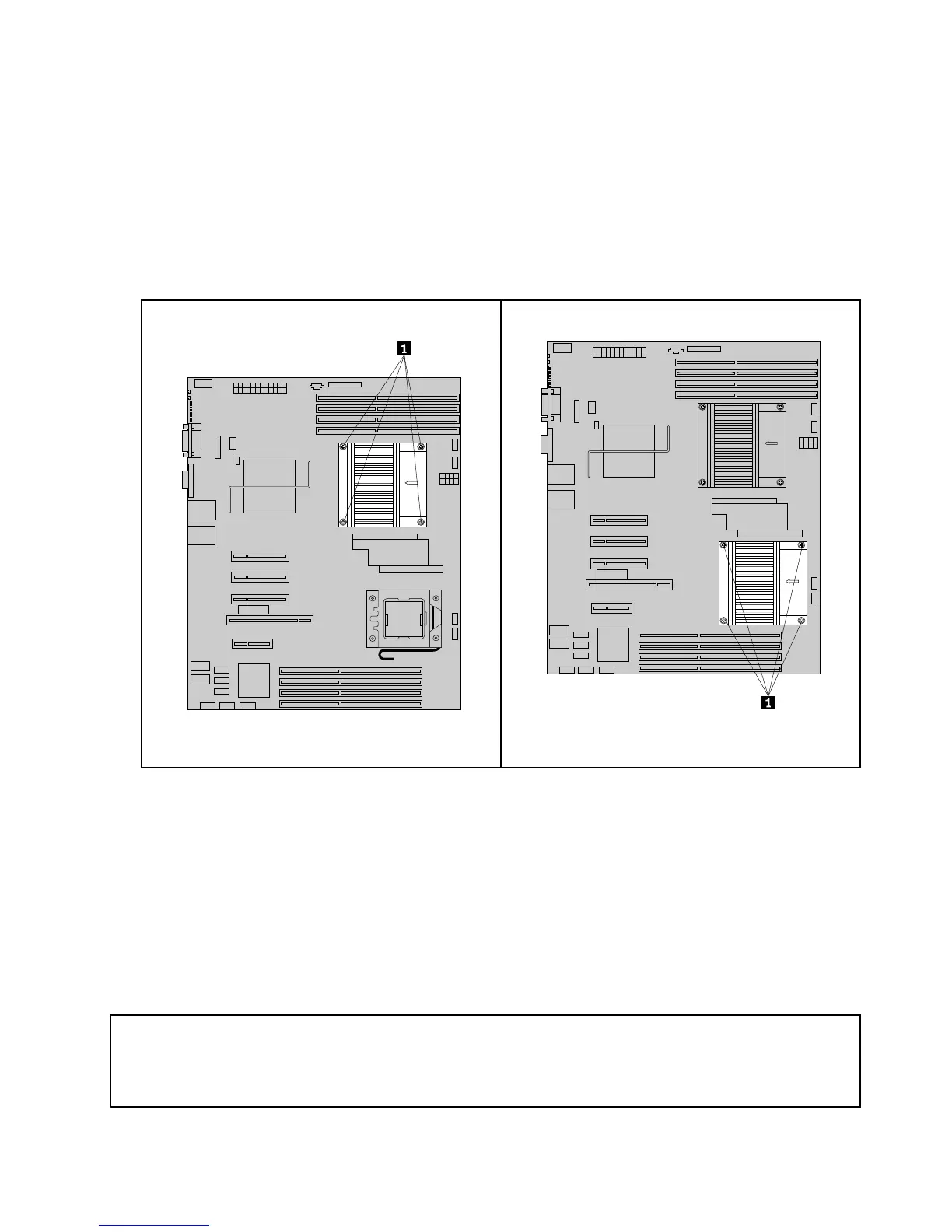
5.Placetheheatsinkandfanassemblyonthesystemboardsothatthefourscrewsontheheatsinkand
fanassemblyarealignedwiththecorrespondingmountingstudsonthesystemboard.Makesurethat
youproperlyplacetheheatsinkandfanassemblysothatyoucaneasilyconnecttheheatsinkandfan
assemblycabletothesystemfan2connector(iftheheatsinkandfanassemblyisformicroprocessor1)
orthesystemfan1connector(iftheheatsinkandfanassemblyisformicroprocessor2)onthesystem
board.See“Locatingpartsonthesystemboard”onpage33
.
Note:Notetheorientationoftheheatsinkandfanassemblybyreferringtothearrowlabelonthetop
oftheheatsinkandfanassembly.Thearrow,whichindicatesairow,shouldpointtotherearof
thechassis.
Figure67.Screwsthatsecuretheheatsinkandfan
assemblyformicroprocessor1
Figure68.Screwsthatsecuretheheatsinkandfan
assemblyformicroprocessor2
6.Alternatetighteningeachscrewasmallandequalamountuntiltheheatsinkandfanassemblyis
securedtothesystemboard.Donotover-tightenthescrews.
7.Connecttheheatsinkandfanassemblycabletothesystemfan2connector(iftheheatsinkandfan
assemblyisformicroprocessor1)orthesystemfan1connector(iftheheatsinkandfanassemblyisfor
microprocessor2)onthesystemboard.See“Locatingpartsonthesystemboard”onpage33.
8.Tocompletetheinstallation,goto“Completingthepartsreplacement”onpage122.
Removingorinstallingafrontfan
Thissectionprovidesinstructionsonhowtoremoveorinstallafrontfan.
Removingafrontfan
Attention:
DonotopenyourserverorattemptanyrepairbeforereadingandunderstandingtheSafetyInformationandthe
WarrantyandSupportInformationontheThinkServerDocumentationDVDthatcamewithyourproduct,and
“Guidelines”onpage39
.Toobtainacopyofthepublications,goto:
http://www.lenovo.com/support
Chapter5.ReplacingFRUs101

 Loading...