9 Network activity LED (green)
When this LED is lit, it indicates that the server is transmitting to or receiving signals from the Ethernet LAN.
10 Identification button/LED (blue)
Use this blue LED to visually locate the server among other servers. This LED is also used as a presence
detection button. You can use Lenovo XClarity Administrator to light this LED remotely.
11 System error LED (yellow)
When this yellow LED is lit, it indicates that a system error has occurred. This LED can be controlled by the
XCC. Information provided from the LCD display of the LCD diagnostics panel could also help isolate an
error.
13 Rack release latches
Press on the latch on both sides to disengage the server from the rack and slide it out.
LCD diagnostics panel
The LCD diagnostics panel is attached to the front of the server, while it allows quick access to system
information such as errors, system status, firmware, network, and health information.
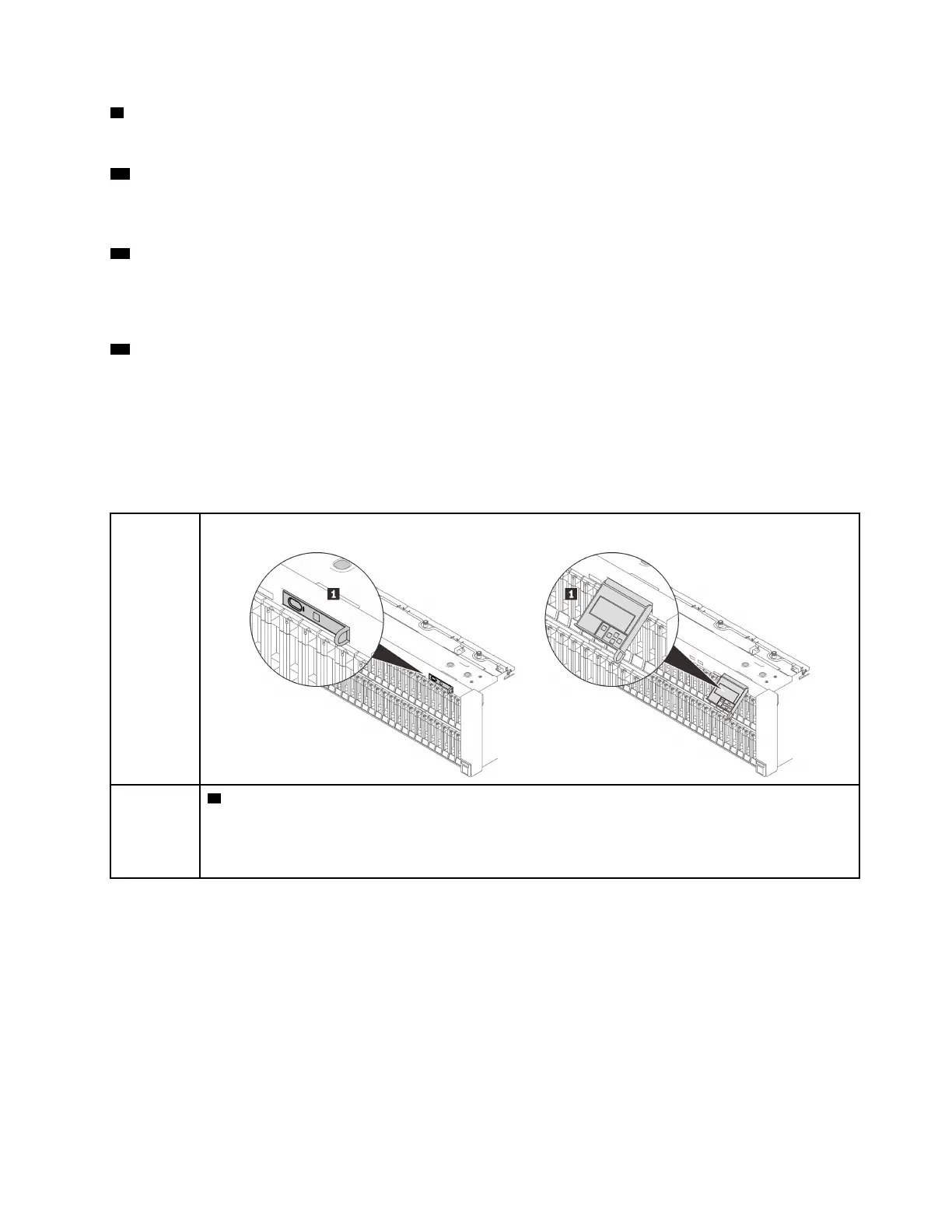
Location of the LCD diagnostics panel
Location
The LCD diagnostics panel is attached to the front of the server.
Callout
1 The handle with which the panel can be pulled out from the server.
Notes:
• The panel can be pushed in or pulled out regardless of the system power status.
• When pulling it out, do it gently to avoid damage.
Chapter 2. Server components 17

 Loading...


