• Youku: http://list.youku.com/albumlist/show/id_50952215
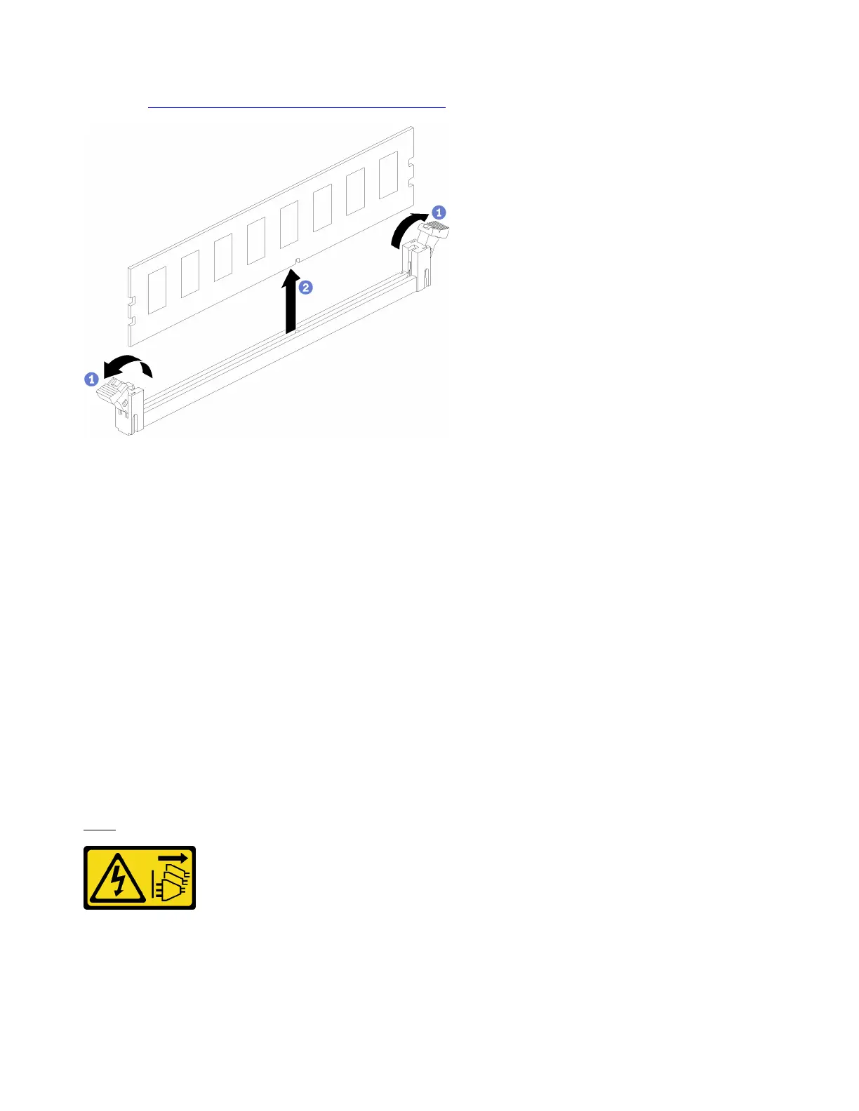
Step 1. Open the memory module connector retaining clips to extract the memory module; then, remove
the memory module.
If you are not replacing the memory module that you removed:
1. See the Lenovo ThinkSystem SR950 Memory Population Reference for the required installation order of
the remaining memory modules.
2. Install a memory module filler, that was originally provided with the PHM option, in any vacant memory
module connectors.
3. Install the upper compute system board or compute system board filler, if it was removed. See “Install a
compute system board” on page 128.
4. Install the compute tray where the compute system board is installed. See “Install the compute tray (fully
removed)” on page 125.
5. Install the front cover. See “Install the front cover” on page 139
If you are instructed to return the memory module, follow all packaging instructions and use any packaging
materials that are provided.
Install a memory module
Memory modules are in the compute system boards that are accessed from the front of the server.
S002
CAUTION:
The power control button on the device and the power switch on the power supply do not turn off the
electrical current that is supplied to the device. The device also might have more than one power
cord. To remove all electrical current from the device, ensure that all power cords are disconnected
from the power source.
166
ThinkSystem SR950 Setup Guide

 Loading...


