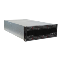
Front view of server
Figure 4 “Front view of the server (front cover installed)” on page 17 illustrates the front view of the server,
with the front cover installed, identifying the drive bays.
Figure 4. Front view of the server (front cover installed)
Figure 5 “Front view of the server (front cover removed)” on page 17 illustrates the front view of the server.
Figure 5. Front view of the server (front cover removed)
Table 2. Components on the front of the server
Callout Callout
1 2.5-inch-drive bays (12–23) (some models) 7 Power button and power LED (see “Front operator
panel” on page 18)
2 Fans (1–12) 8 Front operator panel with pull-out LCD display (see
“LCD system information display panel” on page 19)
3 2.5-inch-drive bays (0–11) 9 USB 2.0 port
4 System-error LED (see “Front operator panel” on page
18)
10 USB 2.0 Lenovo XClarity Controller management port
(see “Set front USB port for Lenovo XClarity Controller
connection” on page 87)
5 System ID button/LED (see “Front operator panel” on
page 18)
11 VGA Video port
6 Network activity LED (see “Front operator panel” on
page 18)
Chapter 2. Server components 17

 Loading...


