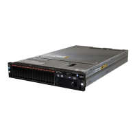
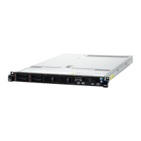
Figure76.FrontUSBassemblyremoval
Step6.IfyouareinstructedtoreturnthefrontUSBassembly,followallpackaginginstructions,anduse
anypackagingmaterialsforshippingthataresuppliedtoyou.
ReplacingthefrontUSBassembly
UsethisinformationtoreplacethefrontUSBassembly.
ToinstallthefrontUSBassembly,completethefollowingsteps.
Step1.Readthesafetyinformationthatbeginson“Safety”onpagevand“Installationguidelines”on
page289
.
Step2.Turnofftheserverandperipheraldevicesanddisconnectthepowercordsandallexternalcables,
ifnecessary.
Step3.Removethetopcover(see“Removingthetopcover”onpage143).
Step4.AlignandslidethefrontUSBassemblyintotheserveruntilitclicksintoplace.
Figure77.FrontUSBassemblyinstallation
Step5.ConnectthecableonthefrontUSBassemblytothesystemboard.
ThefollowingillustrationshowsthecableroutingforthefrontUSBassembly.
150LenovoSystemx3650M5InstallationandServiceGuide

 Loading...


