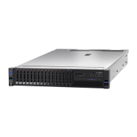
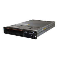
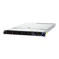
Figure118.PCIriser-cardadapterexpansionslotlocations
Thefollowingtabledescribesthemaximalcarddimensionsupportedineachslot.
Table14.Themaximalcarddimensionsupportedineachslot
Riser-cardassembly
Slot
numberThemaximalcarddimensionsupported
1
Fullheight,uptofulllength
2
Fullheight,uptofulllength
Riser-cardassembly1
3
Fullheight,halflength
4
Low-profile
5
Low-profile
6
Fullheight,uptofulllength
7
Fullheight,uptofulllength
Riser-cardassembly2
8
Fullheight,halflength
Note:Ifyouarereplacingahighpowergraphicsadapter,youmightneedtodisconnecttheinternalpower
cablefromthesystemboardbeforeremovingtheadapter.
Toremoveanadapter,completethefollowingsteps:
Step1.Readthesafetyinformationthatbeginson“Safety”onpagevand“Installationguidelines”on
page289.
Step2.Turnofftheserverandperipheraldevicesanddisconnectallpowercords;then,removethetop
cover(see“Removingthetopcover”onpage143).
Step3.Pressdownontheleftandrightsidelatchesandslidetheserveroutoftherackenclosureuntil
bothsliderailslock;then,removethetopcover(see“Removingthetopcover”onpage143).
Step4.Removetheriser-cardassemblythatcontainstheadapter(see“Removingariser-cardassembly”
onpage179
).
•IfyouareremovinganadapterfromPCIexpansionslot1,2,or3,removeriser-cardassembly1.
186LenovoSystemx3650M5InstallationandServiceGuide

 Loading...


