Wiring the standard device
Basics for wiring according to EMC
Control cables
5
5.2
5.2.4
5.2-3
EDSVF9333V EN 3.0-06/2005
5.2.4 Control cables
ƒ Control cables must be shielded to minimise interference injections.
ƒ For lengths of 200 mm and more, use only shielded cables for analog
and digital inputs and outputs. U nder 200 mm, unshielded but twisted
cables may be used.
ƒ Place the shield correctly:
– The shield connections of the control cables must be at a distance of
at least 50 mm from the shield connections of the motor cables and
DC cables.
– For cables for digital inputs and outputs, place the shield at both
ends.
– For cables for analog inputs and outputs, place the shield at one end
on the drive controller.
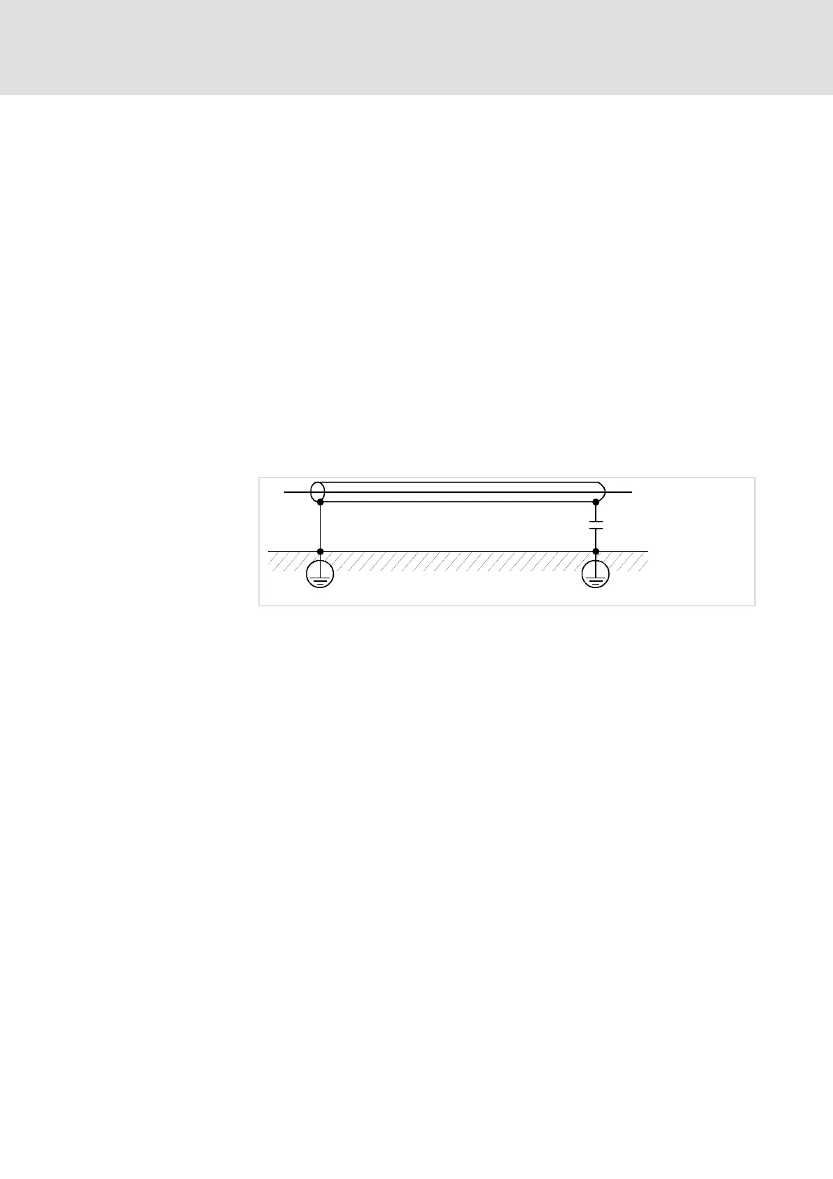
ƒ To achieve an optimum shielding effect (in case of very long cables,
with high interference) one shield end can be connected to PE potential
via a capacitor (e.g. 10 nF/250 V) (see sketch).
Fig. 5.2-2 Shielding of long, analog control cables