Free connection of analog signals
Free configuration of analog outputs
10
Function library
10.12
10.12.2
L
10.12-8
EDS82EV903-1.0-11/2002
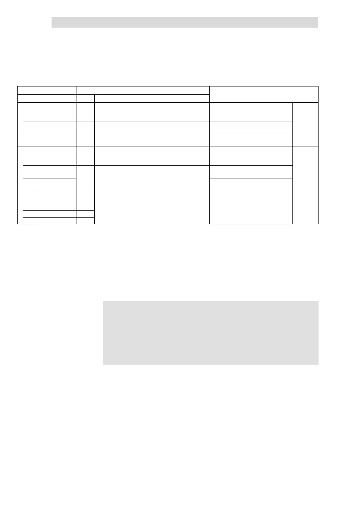
Code IMPORTANTPossible settings
No. SelectionLenzeName
C0420*
(A)
46
Gain analog output s
Applicat ion I/O
128 ≡ Gain 1
^
10.12-4
1 X3/62
(AOUT1-GAIN)
128
0 {1} 255 C0420/1 and C0108 are the same
2 X3/63
(AOUT2-GAIN)
C0422*
(A)
47
Offset analog
outputs
Application-I/O
^
10.12-4
1 X3/62
(AOUT1-OFFSET)
0.00
-10.00 {0.01 V} 10.00 C0422/1 and C0109 are the same
2 X3/63
(AOUT2-OFFSET)
C0424*
v
(A)
Output signal range
- analog outputs
Application–I/O
Observe the jumper setting of the function
module!
(as of version application-I/O E82ZAFA ...
^
10.12-4
1 X3/62 (AOUT1) 0 0 0 ... 10 V / 0 ... 20 mA
x11)
2 X3/63 (AOUT2) 0 1 4 ... 20 mA
The analog outputs are linked with internal analog signals by entering the
selection figure of the internal signal into the corresponding subcode of C0419.
C0419 can be different for the parameter sets.
l C0419/1 ð 51: The process data word CAN-IN2/word 2 is the signal
source for X3/62.
l C0419/2 ð 5: The monitoring signal “Motor voltage” is the signal source for
X3/63.
)
))
) Note!
The process data input words CAN-IN1.W1/FIF-IN.W1,
CAN-IN1.W2/FIF-IN.W2, CAN-IN2.W1 and CAN-IN2.W2 can be
defined as analog word or digital word (16 bit). If you link them
with analog outputs (C0419/x = 50, 51 or 60, 61), they must be
defined as analog input words. Otherwise the output signal would
be incorrect.
Set gain (C0420)and offset (C0422) to adapt the output signal to the application.
The normalisation of the output signal indicated under C0419 refer to gain 1
(C0420 = 128).
Signal linkage
Examples
Adjustment