Braking operation with three-phase AC brake motor
13
Braking operation
13.3
L
13.3-2
EDS82EV903-1.0-11/2002
The following table shows control possibilities for Lenze spring-operated brakes
via the relay output of the controller. The indications made refer to a rated mains
voltage of 230 V ±10 % or 400 V ±10 %:
Brake motor
Brake size 06 08 10 12 14 16 18
Brake torque 4Nm 8Nm 16 Nm 32 Nm 60 Nm 80 Nm 150 Nm
Motor frame size 063
071
080
090
090
100
100 112
132
132
160
160
Switching via controller relay output ... a
coil
Rectifier
AC switching 180 V Single-way
(E82ZWBR3)
¨ ¨ ¨
205 V Bridge (E82ZWBR1) þ þ þ
DC switching 180 V Single-way
(E82ZWBR3)
¨ ¨ ¨
205 V Bridge (E82ZWBR1) þ þ
1)
¨
Direct DC switching 180 V Not necessary þ
1)
þ
1), 2)
¨
205 V Not necessary þ
1)
þ
1), 2)
¨
24 V Not necessar y þ
1)
þ
1), 2)
¨
þ Permissible
¨ Only permissible with additional relay
1)
8200 vector 0.25 ... 11 kW: Switching is only permissible with additional
auxiliary relay
2)
Spark suppressor must be used
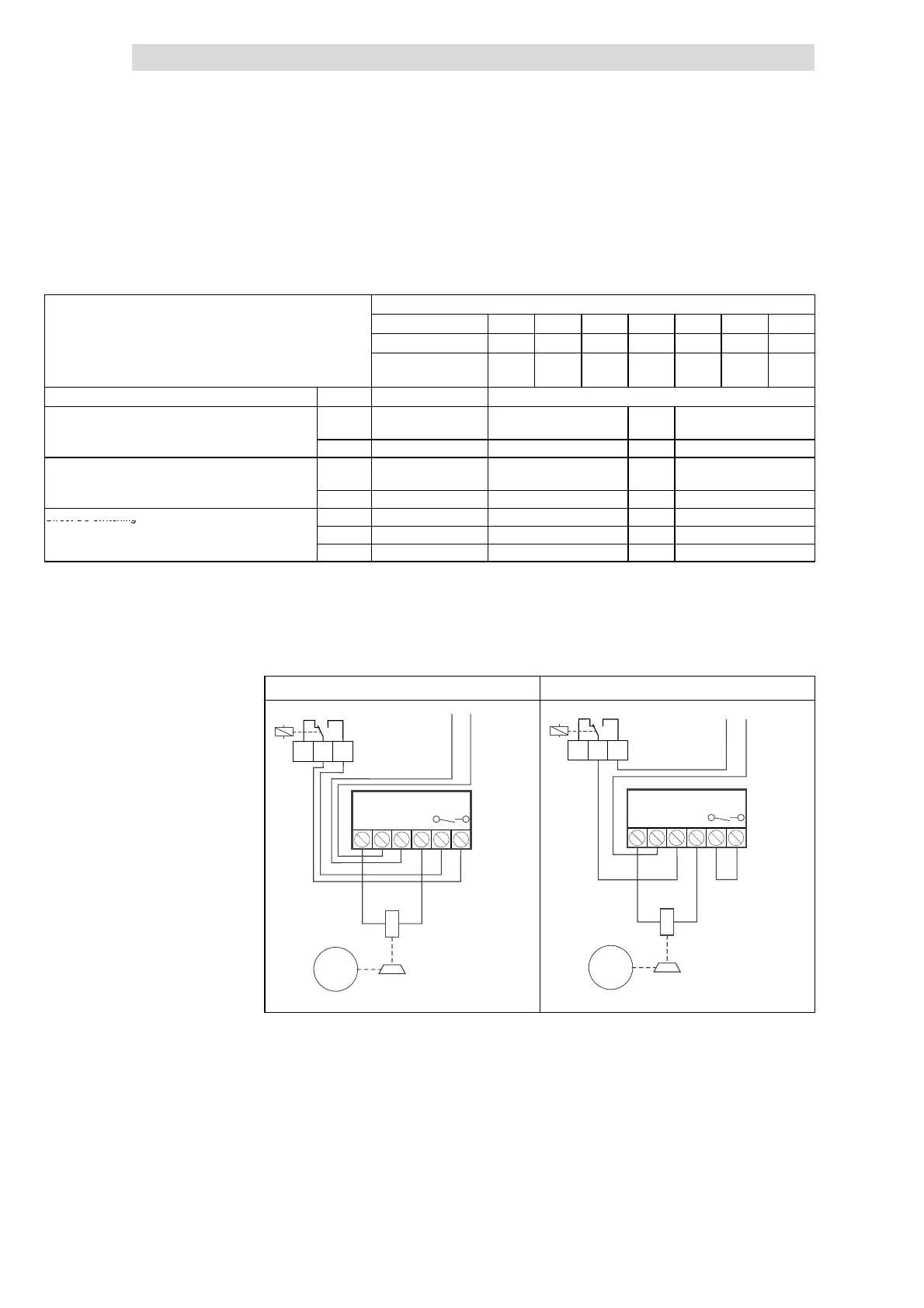
DC switching (quick brake reaction)
AC switching (delayed brake reaction)
205 V
-
~~
+
E82ZMBR1
M
3~
X1
K14K12K11
f < C0017 f C0017≥
AC
230 V
205 V
-
~~
+
E82ZMBR1
M
3~
X1
K14K12K11
f < C0017 f C0017≥
AC
230 V
82ZMBR1_001 82ZMBR1_002
In order to control the brake via the relay output of the controller you must
parameterise the relay output accordingly.
The brake is to be released/applied, when a defined output frequency is
exceeded/not reached. For this use the signal ”Value below Qmin threshold”:
l Use C0008 = 7 to assign the signal “Value below Q
min
threshold” to the
relay output.
l Use C0017 to set the frequency threshold Q
min
Controlling the brake via the
relay output
Wiring
Parameter setting of the relay
output
Example