Braking operation with external brake resistor
Wiring of brake resistor
13
Braking operation
13.4
13.4.5
L
13.4-11
EDS82EV903-1.0-11/2002
T1
T2
R
B
ϑ >
PES PES
PES PES
L ≤ 8m
RB1 RB2
ERBS002
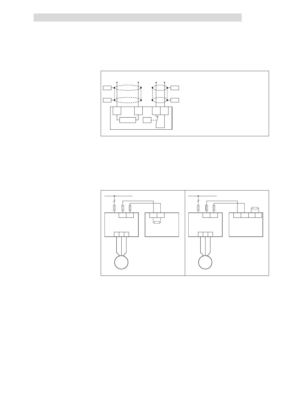
Fig. 13.4-1 Wiring of brake transistor with 8200 vector 0.25 ... 11 kW
PES HF-shield end by PE connection through shield bracket.
RB1, RB2 Brake resistor terminals
Controller supply
T1, T2 Terminals of temperature monitoring of the brake resistor
(thermostat/NC contact)
Supply for evaluating temperature monitoring
(can be integrated e.g. into the lock of the mains contactor lock of
the mains supply)
U
V W
-UG -UG
R
B
+UG +UG
M
3~
8200 vector
E82EVxxxK4B EMB9351-B
3/PE AC 400/500 V
F1 ... F3
F4
3
F5
47
U
V W
-UG -UG RB2
R
B
≥Ω18
+UG +UG RB1
M
3~
8200 vector
E82EVxxxK4B EMB9352-B
3/PE AC 400/500 V
F1 ... F3
F4
3
F5
8200vec541 8200vec542
Fig. 13.4-2 Connection of the brake resistor to 8200 vector 15 ... 90 kW
Schematic diagram: Connection
to brake transistor
Schematic diagram: Connection
to brake module and brake
chopper