Parameterising analog modules
Parameter data
13
Parameter setting via PROFIBUS−DP
13.1
13.1.1
L
13.1−3
EDSPM−TXXX−9.0−11/2009
l
For a 4×analog output module, 6 bytes of parameter data are available. The
following are defined via the parameter data
– The signal function for each output (current signal output, voltage signal
output),
– The module error behaviour.
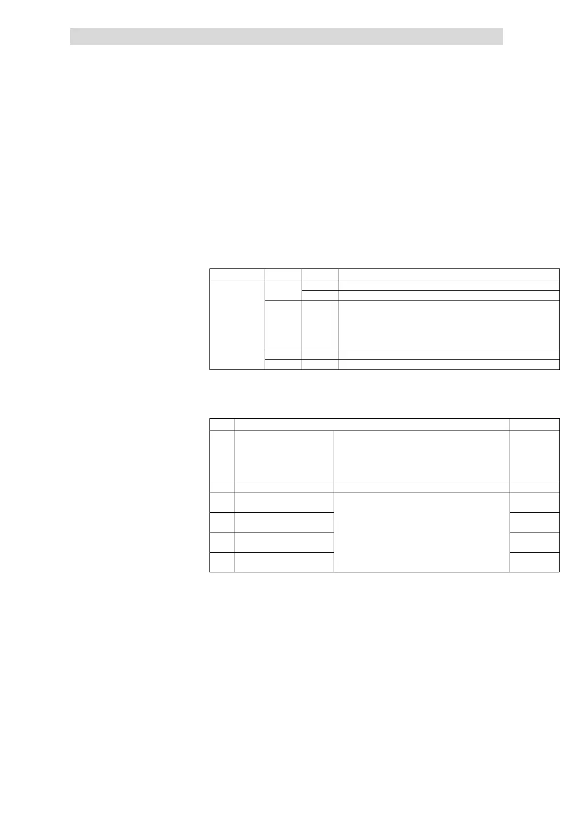
l The module can be parameterised with the configuration tool or via slot and
index.
– To set the parameters via slot and index, the function blocks SFB 52 (read)
and SFB 53 (write) are required.
Slot number Index Access Description
1 ... 32 00
h
R Read out diagnostic data record 0
W Write parameters to the module
01
h
R The corresponding diagnostic data record of the electronic module can be
read out via the index.
· Example:
– Index 01
h
: read out diagnostic data record 1
– Index 02
h
: read out diagnostic data record 2
F1
h
R Read out the module parameters
F2
h
R Read out the process image of the module
R = read
W = write
The following bytes with fixed assignment are available for parameter data:
Byte Assignment Lenze setting
0 Enabling/inhibiting diagnostic
alarm
1)
Bits 0 ...
5 %
Reserved
00
h
Bit 6
0 Alarm inhibited
12.3−6
1 Alarm enabled
Bit7
Reserved
1 Reserved
2 Selecting signal function for
output E.0
Selection of the signal function: 13.1−14
3 Selecting signal function for
output E.1
4 Selecting signal function for
output E.2
5 Selecting signal function for
output E.3
1)
The function is not available for the modules 4×analog output ±10V and 4×analog output 0...20mA.
4xanalog output modules
 Loading...