Mounting and installation
Leuze electronic BPS 8 46
TNT 35/7-24V
In order to select the right mounting location, several factors must be considered:
• The scanning range must be adhered to at all areas at which a position determination
is to be made.
• The BPS should be mounted at an angle of 10° (depending on the tape height, see
note on Page 46) in the horizontal axis relative to the bar code tape to ensure contin-
ued reliable positioning results even in the event of soiling of the bar code tape.
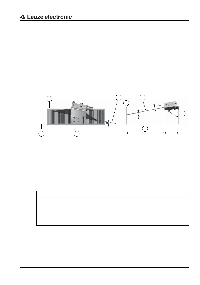
• On the BPS 8, the beam is not emitted perpendicular to the cover of the housing, but
with an angle of about 4°±2° towards the bottom. To achieve a total pitch greater
than/equal to 10°, the mounting bracket MA 8-01 has an angle of about 8°±0.5°. This
angle must not fall below this value. A total reflection of the scanning beam on the bar
code tape is thus prevented. With the angles integrated into the BT 8-01, the BPS 8
can be mounted in parallel to the bar code tape in the reading distance required.
Figure 6.11: Beam exit and device arrangement of the BPS 8 SM 102
NOTE
Angle of inclination!
For the mounting, an angle of inclination of
• 10° for a tape height of 47mm,
• 5° for a tape height of 30mm or 25mm
must be factored in the vertical axis and the working range of the reading field curve.
45 mm
4°
±
2°
12°
±
2.5°
82°
±
0.5°
BPS 8 SM 102
A
B
D
C
E
C
A Bar code tape
B Reference plane
C Pitch of scanning beam:
= 10° for a tape height of 47mm
= 5° for a tape height of 30mm or 25mm
D Reading distance
E BT 8-01 mounting bracket
A
E