4511-xxx
5-4 Service Manual
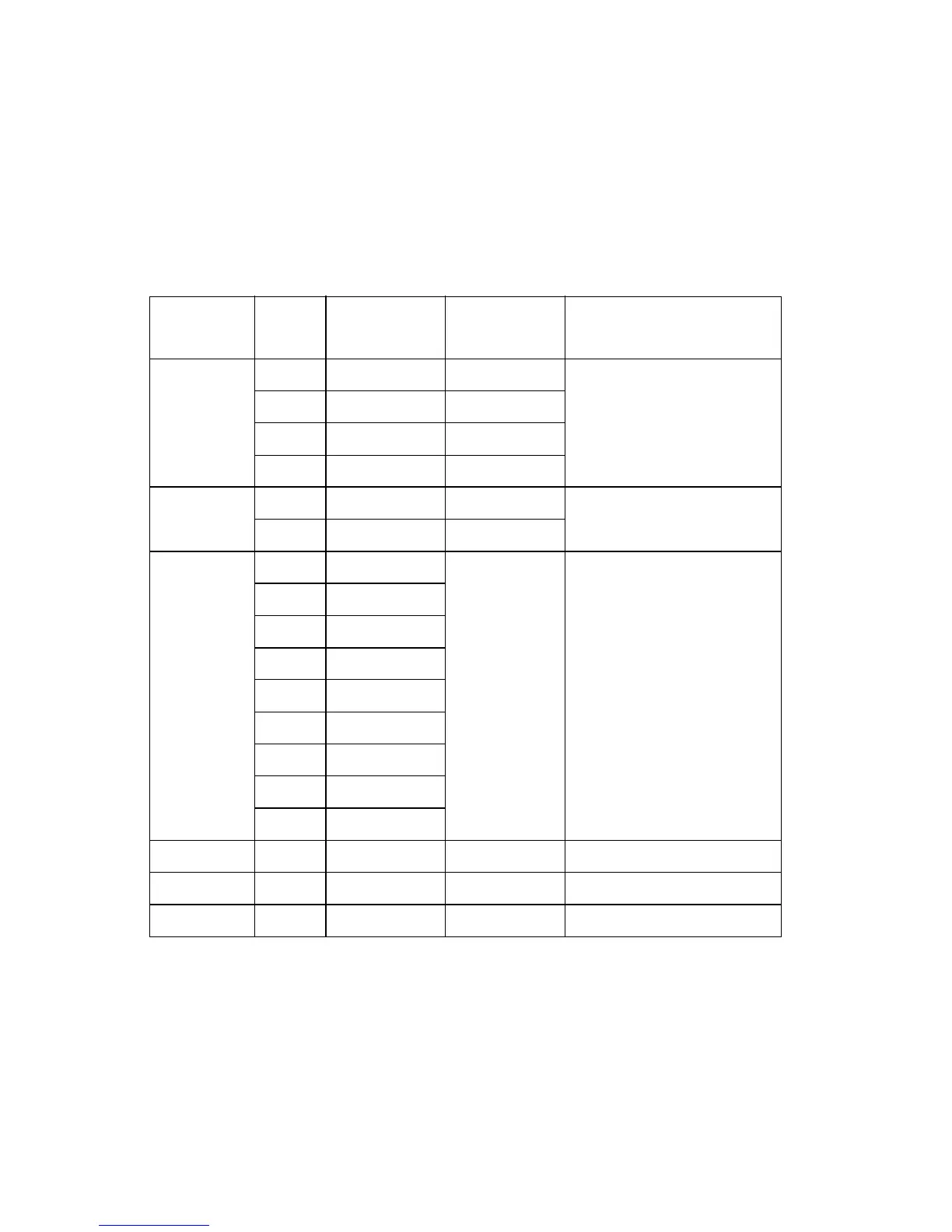
Controller card connector pin values
(Also, see the wiring diagram at back of book.)
These values were measured with all connections made (plugged) or with
only one connector at a time unplugged to expose the pins. Always
disconnect and connect with the printer power off. Otherwise, the values
below may not match.
Connector Pin #
Value
(plugged)
Value
(unplugged) Comments
J2 1, 4 +5 V dc +5 V dc Without tray 2 attached;
Ready mode
2 +24 V dc +24 V dc
6 Ground Ground
3, 5 Signal Signal
J3 1, 3 +24 V dc +24 V dc Manual and paper feed
solenoids; Ready mode
2, 4 +24 V dc 0 V dc
J4 1, 2 0 V dc Main power
source to
controller
card
LVPS/HVPS; Ready
mode
3. 4 +5 V dc
5, 6 Signal
7 Ground
8, 9 +24 V dc
10 Signal
11 +5
12, 14 Ground
13 Signal
J5 – – – USB port
J6 – – – Network port (Ethernet)
J7 – – – Parallel port