INSTALLATION & SERVICE MANUAL – EASYLIFT – UK VERS 1.5
Liftup A/S Hagensvej 21| DK-9530 Støvring | Denmark | T: +45 96 86 30 20 | M: support@liftup.dk | www.liftup.dk | CVR DK-1015 3964
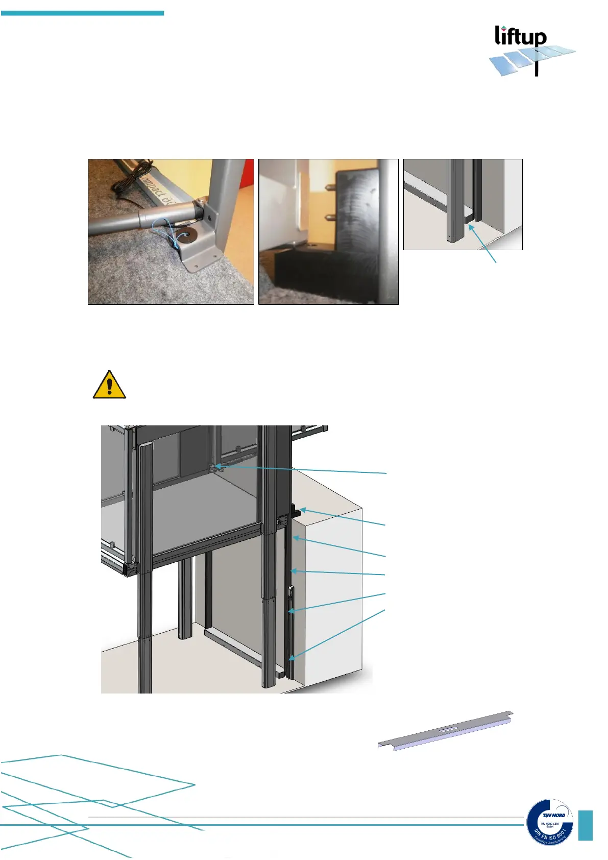
The bracket for the door actuator is attached on the left-hand side and the door contact is
attached on the right-hand side. When both wall profiles are attached they should have a
clearance of 10 mm between floor and profile. (If not, you need to cut the wall profile to size).
Use service mode (see chapter 5) to run the lift to top position.
Once the lift is in the position as the picture below, you can fix the wall profiles (left and right)
to the wall.
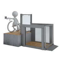
ATTENTION! Make sure that the wall profiles are 100% vertically mounted, and
the distance between them is exact.
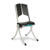
Remember to use the mounting guides or respect the
following distance between the wall profiles: 800 mm
between wall profiles for the EasyLift 800 and 900 mm for
the EasyLift 900.
Bracket for fixing
the door and the
motor
Fixing points: Use the
appropriate fixing screw,
adapted to the wall