LIGHTMED TruScan Pro – Operator’s Manual Rev. No. 01 Page 6 of 109
List of Drawings / Figures
Safety Controls and Features
Laser Console Safety Labels (Bottom Panel)
Laser Console Safety Labels (Back Panel)
Slit Lamp LDU With Labels
System Software Start-Up Screen
System Software Display When In “STANDBY” Mode
User Mode Screen Display Divided into Three Panes
Pattern Scanner Panel Controls
Packing Carton for the Table Assembly
Portable Carrying Case for TruScan Console
Remove the foam packaging
Loosening Two Spring-Loaded Screws on the Left Console Holder Cover
Removing the Cover from the Table
Removing the Cable Cover underneath the Tabletop
Feeding Remote Cable from the Console Cavity to the Tabletop
Routing the Cable and Fiber from the Slit Lamp
Screwing the Metal Cable Cover Plate Back onto the Tabletop
Attaching the Chinrest to the Tabletop
Slit Lamp and Chinrest Cable Management
Connecting the Slip Lamp Ground and Fixation Lamp Cables
Mounting the LCD Screen onto the Tabletop
Mounting the LCD Screen onto the Arm
Connecting LCD Screen Cables
Mounting the Laser Console to the Console Hanger
Connecting the Cables to the Laser Console
Releasing Console Hanger from the Stopper
Pushing the Console Hanger Back into the Console Cavity
Inserting the Fiber Assembly into Port 1 of the Laser Console
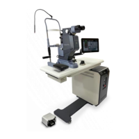
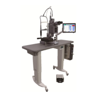
Final Assembly of the TruScan Pro System
Endoprobe Coupling Plug Assembly